You need straight bevel pitch cones, blank ODs, mounting distance, face/virtual teeth, or a first-pass Lewis check with axial thrust before you freeze a right-angle drive. This pad covers six input modes — pitch cones, blank geometry, Strength (Lewis), mounting distance, face & virtual teeth, and force triangle — each with a distinct animated 2D Results sketch.
Defaults open on Pitch cones: m = 4 mm, 20/40 teeth, Σ = 90°, face 25 mm. CALCULATE returns pitch diameters 80 / 160 mm, cone angles ≈ 26.57° / 63.43°, cone distance R ≈ 89.44 mm. Switch to Blank for tip ODs, Mounting for A = R, or Strength for mean-section Lewis with Ft/Fa/Fr. Math stays in your browser.
It sits under Mechanical Calculators next to the spur gear calculator, helical gear calculator, and gear ratio calculator.
Formula
- Pitch diameters: d1 = m·Z1, d2 = m·Z2 (large-end module).
- Cone angles: tan δ1 = sinΣ / (i + cosΣ), δ2 = Σ − δ1, with i = Z2/Z1. At Σ = 90°, tan δ1 = Z1/Z2.
- Cone distance: R = d1/(2 sin δ1) = d2/(2 sin δ2). At 90°, also R = 0.5·m·√(Z1²+Z2²).
- Tip OD: da = d + 2·m·cosδ. Back-cone radius Rb = (d/2)/cosδ. Virtual teeth zv = Z/cosδ.
- Face guide: b ≤ R/3. Mounting distance with zero hub offset: A = R. Apex axial offset R·cosδ.
- Forces: Fa = Ft·tanα·sinδ, Fr = Ft·tanα·cosδ. Lewis: mm = m(R−b/2)/R, σ = Ft/(Cv·b·mm·Y).
Reproduce the default Pitch cones path on CALCULATE:
| Quantity | Value |
|---|---|
| m / Z1 / Z2 / Σ | 4 mm · 20 / 40 · 90° |
| Pitch diameters | 80 / 160 mm |
| Cone angles δ1 / δ2 | ≈ 26.57° / 63.43° |
| Cone distance R | ≈ 89.44 mm |
| Tip ODs (Blank mode) | ≈ 87.16 / 163.58 mm |
| b/R (face 25 mm) | ≈ 0.280 (under 1/3) |
How it works
Pick Pitch cones, Blank, Strength (Lewis), Mounting distance, Face & virtual teeth, or Force triangle. Straight bevel for intersecting shafts: δ1/δ2, R, tip ODs, zv, b≤R/3, A=R (h=0), mean-section Lewis, and Ft/Fa/Fr. Each mode draws a distinct animated 2D Results sketch.
Pick Input mode: Pitch cones (default), Blank geometry, Strength (Lewis), Mounting distance, Face & virtual teeth, or Force triangle. The animated 2D sketch in Results switches with the mode (Play/Pause). Enter large-end module, pinion and gear teeth, shaft angle Σ (1–170°), and face width. Face width required for Strength, Face, and Forces. CALCULATE fills Results. Editing clears Results. RESET restores m4 · 20/40 · Σ90 · b25.
Pitch cones share one apex
Bevel layout starts from two touching pitch cones. The shaft angle Σ is usually 90°. Cone angles follow tan δ1 = sinΣ/(i+cosΣ) with i = Z2/Z1; at right angle that collapses to tan δ1 = Z1/Z2.
Defaults 20/40 at 90° give δ1 ≈ 26.57° and δ2 ≈ 63.43°. Outer cone distance R ≈ 89.44 mm is shared by both members — the slant from apex to the large-end pitch circle.
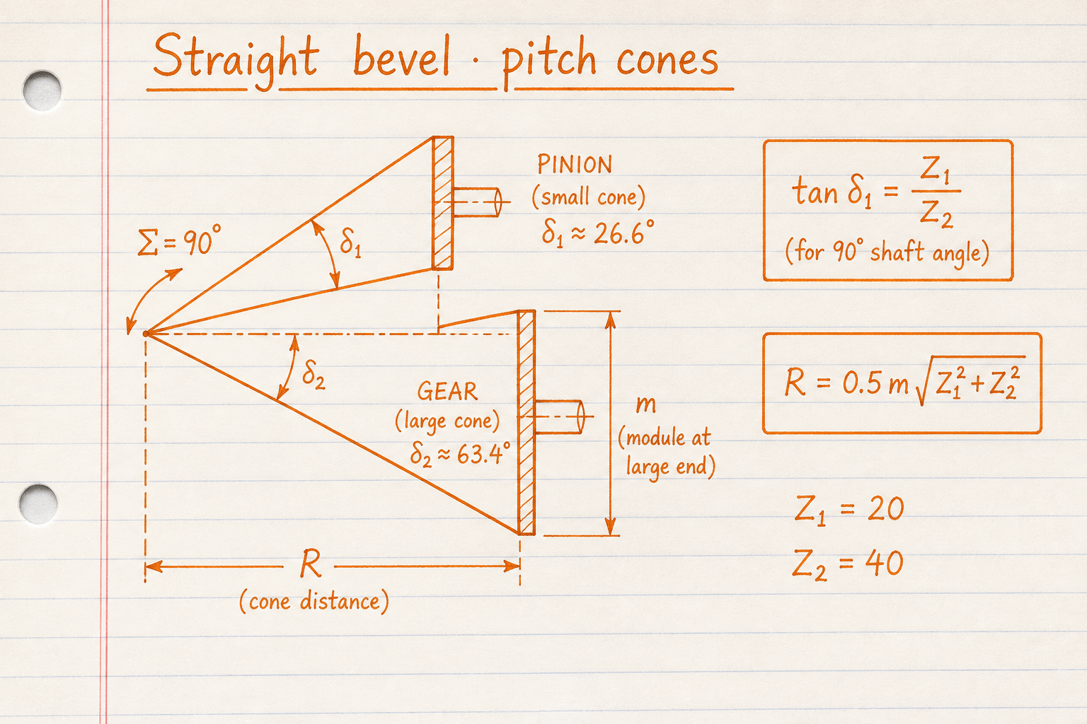
Face width is measured along the cone generatrix. Keep b ≤ R/3.
Changing Σ tilts the axes; δ1 and δ2 always sum to Σ.
Large-end module sets blank diameters
Shop practice sizes the large end first: d = m·Z, da = d + 2m cosδ, back-cone radius Rb = (d/2)/cosδ, and virtual teeth zv = Z/cosδ for formative spur strength.
Default pinion: d = 80 mm, da ≈ 87.16 mm, zv ≈ 22.4. Dedendum stays 1.25m on this pad (full-depth proportions).
Default pair vs miter:
| Case | Inputs | Key result |
|---|---|---|
| Default | 20/40 · m4 · Σ90° | δ ≈ 26.6°/63.4° · R ≈ 89.4 mm |
| Miter | 20/20 · m3 · Σ90° | δ = 45°/45° · R ≈ 42.4 mm |
| Wide face | b = 35 on default | b/R warn (> 1/3) |
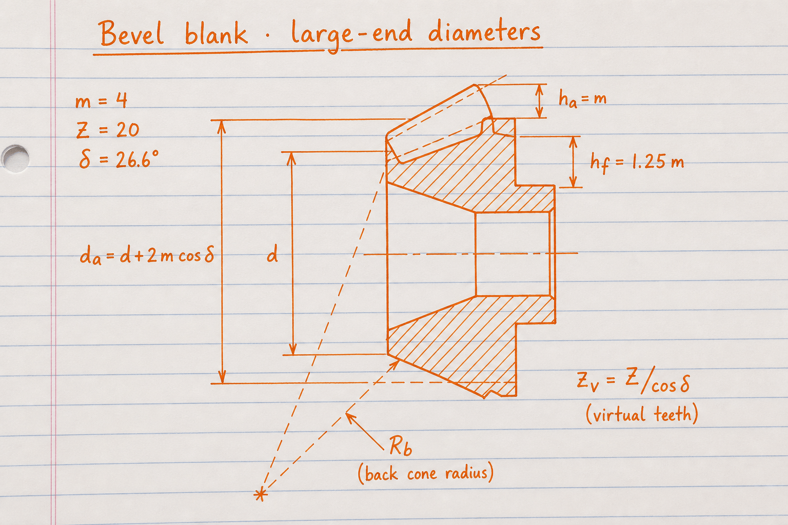
Module is always the large-end module unless you state otherwise.
Virtual teeth feed the Lewis Y lookup in Strength mode.
Mounting distance is not centre distance
Mounting distance A is measured from a mounting datum to the pitch-cone apex. With zero hub/datum offset this pad reports A = R, plus the axial apex offset R·cosδ from the large-end pitch plane.
Spiral, Zerol, and hypoid corrections (and full shaft-load bevel models) are out of scope — this pad is straight bevel geometry and a Lewis screen only.
Lewis at the mean section, not ISO 10300
Strength evaluation often integrates load along the face and evaluates at mid-width. This pad’s Strength mode uses mean module mm = m(R−b/2)/R, Y from pinion zv, Cv = 3/(3+v), and Fa/Fr = Ft·tanα·sinδ / cosδ. Force triangle mode returns Ft/Fa/Fr without FoS.
Example path: m4, 20/40, b = 25 mm, 3 kW at 1000 rpm, allowable 140 MPa → Ft ≈ 833 N, σ ≈ 70.5 MPa, FoS ≈ 1.99 (Pass at ≥ 1.5). Full ISO 10300 / AGMA bevel rating is not computed.
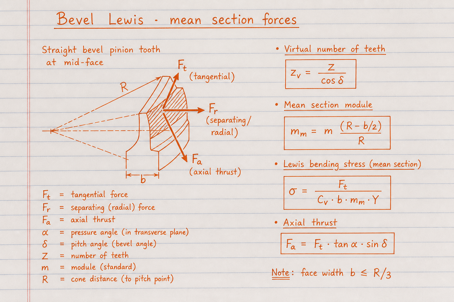
Axial thrust Fa loads bearings along the pinion shaft.
Use FoS as a preliminary go/no-go before a catalog or ISO 10300 worksheet.
What this pad does not generate
CAD tooth-profile scripts, spiral/hypoid geometry, and third-party product configurators are out of scope. Use this pad for straight bevel cones, blanks, face check, mounting distance (h = 0), and Lewis screening — then hand off to CAD or a signed rating.
Worked example
Default Pitch cones: m = 4 mm, Z1 = 20, Z2 = 40, Σ = 90°, b = 25 mm. Reproduce on CALCULATE.
- Leave Input mode on Pitch cones, 20° pressure angle.
- Confirm module 4, pinion 20, gear 40, shaft angle 90, face 25.
- CALCULATE. d = 80 / 160 mm, δ ≈ 26.57° / 63.43°, R ≈ 89.44 mm.
- Switch to Blank for tip ODs ≈ 87.16 / 163.58 mm, or Mounting for A ≈ 89.44 mm.
- Optional: Strength · 3 kW · 1000 rpm · 140 MPa → FoS ≈ 1.99 Pass.
Result: Default: R ≈ 89.44 mm, i = 2. Strength example: FoS ≈ 1.99 on the 3 kW example.
When to use
- Sizing straight bevel pitch cones for intersecting shafts
- Checking face width against R/3 before ordering blanks
- Computing tip OD, back-cone radius, and virtual teeth
- Estimating geometric mounting distance with zero hub offset
- First-pass Lewis FoS or Ft/Fa/Fr forces on the pinion
Limitations
- Straight bevel only. No spiral, Zerol, hypoid, or non-intersecting axes.
- No profile shift, backlash design, or tooth-form export.
- Mounting distance assumes zero hub/datum offset (A = R); real drawings add offset h.
- Lewis + Barth Cv is a preliminary bending screen, not ISO 10300 / AGMA bevel rating.
- Lewis Y uses the common 20° table on virtual teeth for all pressure angles.
- Not a substitute for a signed gearbox selection on safety-critical drives.
FAQ
- How do I calculate bevel gear pitch cone angle?
- For general shaft angle: tan δ1 = sinΣ / ((Z2/Z1) + cosΣ), then δ2 = Σ − δ1. At 90°, tan δ1 = Z1/Z2.
- What is cone distance R?
- The slant from the common pitch-cone apex to the large-end pitch circle: R = d1/(2 sin δ1). At 90°, R = 0.5·m·√(Z1²+Z2²).
- How wide can the face be?
- Keep b ≤ R/3. This pad warns when face width exceeds that guide — use Face & virtual teeth mode to focus on b/R and zv.
- Is mounting distance the same as centre distance?
- No. Mounting distance is axial (datum to pitch-cone apex) for one bevel member. Centre distance is for parallel-shaft pairs.
- What are virtual teeth?
- zv = Z/cosδ — the formative spur tooth count used for Lewis Y and undercut intuition.
- Is this ISO 10300 strength?
- No. Strength mode is Lewis at the mean section with Ft/Fa/Fr. ISO 10300 / AGMA bevel ratings are not computed.
Spur Gear Design Calculator
ISO 53 spur blank, pair a/εα, tooth proportions, Lewis bending, and Ft/Fr force triangle — six modes with 2D sketches.
Open calculatorHelical Gear Design Calculator
ISO-style helical blank, pair a/εγ, lead, contact ratios, Lewis bending, and Ft/Fa/Fr force triangle — six modes with 2D sketches.
Open calculatorGear Ratio Calculator
Gear ratio, output RPM, and torque for spur pairs, compound trains, direct ratio, speed solve, or idler trains.
Open calculator