You need a first-pass gear ratio before you pick a motor, check a replacement pair, or size a short compound or idler train. This pad covers six input modes — pair by teeth, pair by pitch diameter, two-stage compound, direct ratio, from speeds, and idler train — then returns overall ratio, mechanical advantage, output speed, output torque, speed change, and output direction.
Defaults open on Pair by teeth: 20T driver, 60T driven, 1450 rpm, 10 N·m, 100% efficiency. CALCULATE returns ratio 3.0:1, output about 483 rpm, output torque 30 N·m, and 66.7% speed reduction. Each mode draws a distinct animated 2D Results sketch. Math stays in your browser.
It sits under Mechanical Calculators next to the gear train calculator, motor gearbox calculator, and belt drive calculator. This pad is a machine-design ratio check, not a vehicle MPH table from axle and tire height.
Formula
- Pair by teeth / idler train: i = Z_driven / Z_driver. Pair by diameter: i = d_driven / d_driver (same module assumed).
- Compound (2 stages): i_total = (Z2/Z1) × (Z4/Z3). Stage 2 driver shares a shaft with stage 1 driven.
- Direct ratio: enter i. From speeds: i = n_in / n_out (target).
- Output speed n_out = n_in / i. Output torque T_out = T_in × i × η (η = efficiency as a fraction).
- Mechanical advantage for torque equals i on this pad. Speed reduction % = (1 − 1/i) × 100 when i > 1.
- Idler gears do not change i. Each mesh flips rotation; odd mesh count → opposite to input, even → same.
Reproduce the default Pair by teeth path on CALCULATE:
| Quantity | Value |
|---|---|
| Z_driver / Z_driven | 20 / 60 |
| Input | 1450 rpm · 10 N·m · η 100% |
| Ratio i | 3.0 : 1 |
| Output speed | ≈ 483.3 rpm |
| Output torque | 30 N·m |
| Speed reduction | 66.7% |
How it works
Pick Pair by teeth, Pair by diameter, Compound (2 stages), Direct ratio, From speeds, or Idler train. Ratio is driven ÷ driver (or product of stage ratios, or n_in/n_out). CALCULATE returns ratio, mechanical advantage, output RPM, output torque with efficiency, speed change, and output direction with optional idlers.
Pick Input mode: Pair by teeth (default), Pair by diameter, Compound (2 stages), Direct ratio, From speeds, or Idler train. The animated 2D sketch in Results switches with the mode (Play/Pause on the diagram). Enter geometry or speeds for the active mode, then input RPM, torque, efficiency, and optional idler count. CALCULATE fills Results. Editing a field clears Results. RESET restores the 20T / 60T defaults.
Driven over driver is the reduction convention
This calculator defines ratio from tooth counts or diameters as driven divided by driver. A 60T driven on a 20T driver is 3:1. The input turns three times for one output turn. Speed drops; ideal torque rises by the same factor.
Some shops write driver:driven as 1:3 instead. On this pad the number shown as i:1 is always driven ÷ driver, so reduction is i > 1 and overdrive is i < 1. Match that convention before you compare to a drawing note.
Same 3:1 path across modes:
| Mode | Inputs | i on this pad |
|---|---|---|
| Pair by teeth | 20T → 60T | 3.0 |
| Pair by diameter | 40 mm → 120 mm | 3.0 |
| Direct ratio | i = 3 | 3.0 |
| From speeds | 1450 → 483.3 rpm | 3.0 |
| Compound | 20/60 × 20/40 | 6.0 |
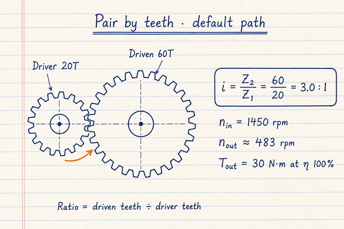
The default pair sketch matches CALCULATE: i = 60/20 = 3, n_out ≈ 483 rpm at 1450 rpm in, T_out = 30 N·m at 100% efficiency.
Switch Input mode to Pair by diameter, Direct ratio, or From speeds when that matches your sketch.
Six input modes, six 2D sketches
Pair by teeth and Pair by diameter size a single mesh. Compound multiplies two stage ratios on a shared intermediate shaft. Direct ratio is for a catalog i you already know. From speeds reverse-solves i = n_in / n_out. Idler train uses the same tooth math as Pair by teeth but draws the idler path and defaults idler count to one so direction flips are obvious.
Direct ratio and From speeds optionally take a driver tooth count to suggest a matching driven tooth count (round of Z₁ × i). For three or four compound stages with per-stage η, open the gear train calculator.
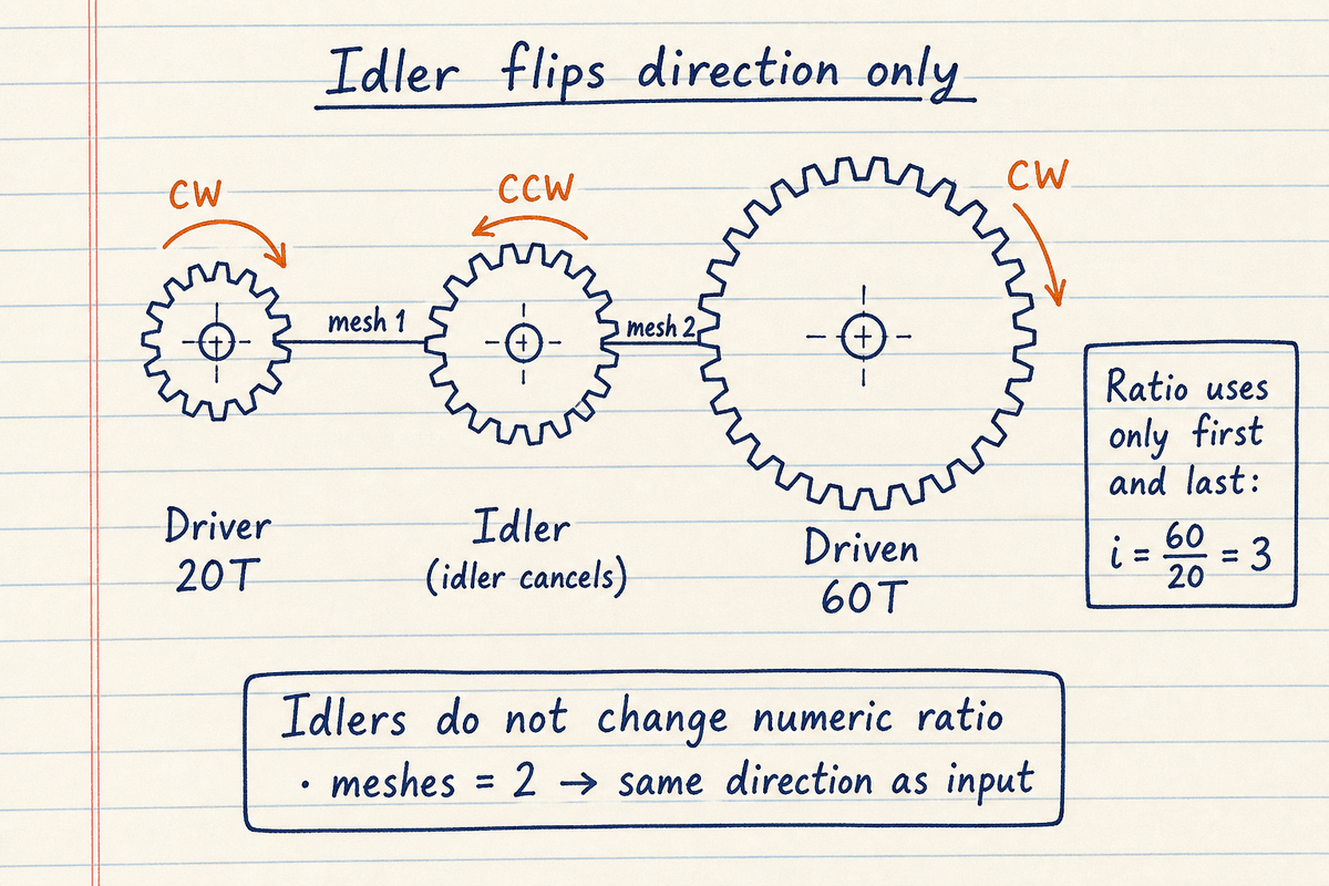
Idler train mode keeps i = Z₂ / Z₁. Extra meshes only reverse rotation (odd → opposite, even → same as input).
Pick Idler train in the pad to see the live 2D path; set Idler gears to match the sketch.
Same ratio from pitch diameters when module matches
When both gears share the same module (or diametral pitch), ratio from pitch diameters equals ratio from teeth: i = d_driven / d_driver. Defaults 40 mm and 120 mm give the same 3:1 as 20T / 60T.
Enter pitch diameters in millimetres on this pad. Do not mix module systems between the two gears and expect the diameter shortcut to hold.
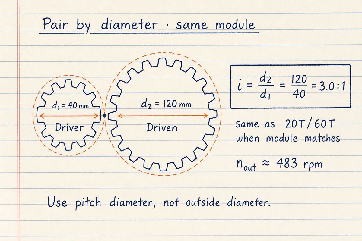
Pitch-diameter mode reproduces the default speed and torque path when diameters are in the same 1:3 proportion as the tooth pair.
Use this sketch when a drawing shows pitch Ø values and not Z counts — not outside diameter.
Compound stages multiply. Idlers only flip direction.
In a compound train, a gear on the same shaft as the previous driven becomes the next driver. Overall ratio is the product of mesh ratios. A 3:1 stage followed by a 2:1 stage is 6:1 overall.
An idler between driver and driven does not change the numeric ratio. It adds a mesh, so rotation direction flips again. On this pad, set Idler gears to count those extras. Odd total meshes → opposite to input. Even → same as input.
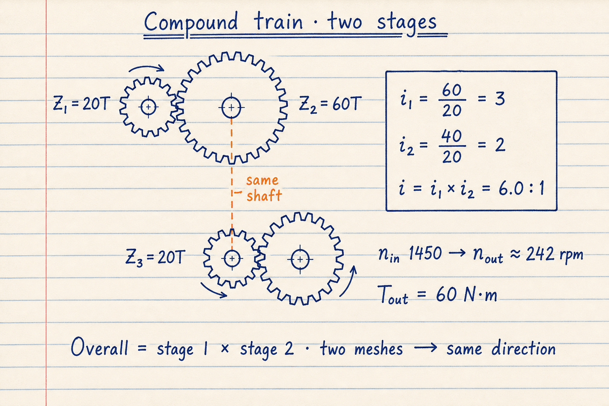
Compound defaults 20/60 × 20/40 give stage ratios 3 and 2, overall i = 6, and n_out ≈ 242 rpm from 1450 rpm.
Two meshes without idlers leave the final shaft turning the same way as the input.
Torque multiplies with efficiency. Stress sizing is separate.
Ideal output torque is T_in × i. Real meshes lose a few percent to friction and churning. Enter efficiency as a percent for the whole path you care about. A 3:1 at 95% turns 5 N·m into 14.25 N·m, not 15.
This pad does not size tooth bending, contact stress, or center distance. After you lock i and speeds, continue with spur/helical geometry tools or a catalog gearbox. Pinions under about 17 teeth on standard full-depth spur profiles can undercut. The pad warns when a stage driver is under 17.
Not a vehicle MPH calculator
Automotive transmission tools combine gear ratios, axle ratio, and tire height to estimate road speed in each gear. That is a different job.
Use this pad for machine shafts, conveyors, and compound spur trains. For motor power after you know load torque and RPM, open the motor gearbox calculator. Chain and belt ratios live on their own pads.
Worked example
Default Pair by teeth: 20T driver, 60T driven, 1450 rpm, 10 N·m, 100% efficiency. Reproduce on CALCULATE.
- Leave Input mode on Pair by teeth. Confirm 20 and 60 teeth, 1450 rpm, 10 N·m, efficiency 100, idlers 0.
- CALCULATE. i = 60/20 = 3.0. The Results 2D mesh spins at the meshed ratio.
- n_out = 1450/3 ≈ 483.3 rpm. T_out = 10 × 3 × 1.0 = 30 N·m.
- Speed reduction = (1 − 1/3) × 100 = 66.7%. Direction opposite (one mesh).
- Optional: Compound 20/60 × 20/40 → i = 6. From speeds 1450 → 483.3 → i ≈ 3. Idler train with 1 idler keeps i = 3 and flips direction.
Result: Default: ratio 3.0:1, ≈ 483 rpm out, 30 N·m. Compound example: overall 6.0:1 ≈ 242 rpm out.
When to use
- First-pass check of a two-gear speed reducer or overdrive
- Verifying replacement tooth counts or pitch diameters
- Entering a known catalog ratio or solving i from speeds
- Estimating output torque before motor or gearbox selection
- Multiplying two compound stages with a shared intermediate shaft
- Checking whether an idler flips output direction without changing ratio
Limitations
- Spur/external mesh model. No planetary, worm, or bevel kinematics.
- Compound mode is two stages. For three or four stages, per-stage η, or richer target-RPM tooth search, use the gear train calculator.
- Does not size tooth bending, contact stress, backlash, or center distance.
- Efficiency is one path number you enter, not a mesh-by-mesh catalog.
- Suggested driven teeth (direct / from-speeds) is a rounded teaching hint, not a mesh-design package.
- Not a vehicle MPH tool (no axle ratio or tire height).
- Not a substitute for a signed gearbox selection on safety-critical drives.
FAQ
- What does a 3:1 gear ratio mean?
- The driver turns three times for every one turn of the driven gear. Output speed is one-third of input speed, and ideal output torque is three times input torque before efficiency.
- Which tooth count goes in the numerator?
- Driven (output) teeth. Driver is the input gear. Ratio = driven ÷ driver on this pad.
- When should I use diameter instead of teeth?
- When you have pitch diameters and the gears share module (or diametral pitch). Ratio of diameters matches ratio of teeth. Outside diameter without pitch diameter is the wrong number.
- How does a compound train work here?
- Enter stage 1 driver/driven and stage 2 driver/driven. Stage 2 driver is the gear on the same shaft as stage 1 driven. Overall ratio is the product of the two stage ratios.
- What are Direct ratio and From speeds for?
- Direct ratio is when you already know i (catalog gearbox). From speeds computes i = n_in / n_out from the speeds you need. Both can suggest a driven tooth count from an optional driver Z₁.
- Do idlers change the gear ratio?
- No. Idlers only add meshes and flip direction. The numeric ratio stays the same. Idler train mode draws that path in the Results sketch.
- How does efficiency affect torque?
- T_out = T_in × i × η. At 95% on a 3:1 with 5 N·m in, output is 14.25 N·m.
- Is this the same as a vehicle speed calculator?
- No. Vehicle speed tools estimate road MPH from transmission, axle, and tire size. This pad is for machine gear pairs and compound spur trains.
- Need more than two compound stages?
- Use the gear train calculator for 1–4 stages with per-stage efficiency, cascade RPM, or a target-RPM reverse solve.
Motor Gearbox Selector Calculator
Motor power from load torque, or gearbox output torque from motor power, ratio, SF, and efficiency.
Open calculatorBelt Drive Calculator
Classical, narrow, cogged, flat, timing, and poly-V belt sizing plus open/crossed length and C from L.
Open calculatorChain Drive Calculator
ANSI roller chain length, pitch diameters, wrap angle, design power, and tensile safety factor.
Open calculator