You have a bracket, flange, or clevis with several bolts and an in-plane shear that does not pass through the pattern centroid. This pad finds the most heavily loaded bolt using the elastic method: equal direct shear plus torsional shear from Mz about the centroid.
Defaults open on Metric rectangular 2×2, pitch 100×100 mm, Vy = 8000 N, ex = 25 mm. CALCULATE returns J = 20,000 mm², Mz = 200,000 N·mm, max Vres ≈ 2549.5 N on the critical bolts at x = −50 mm. Switch to circular or custom coordinates for flange and irregular layouts. Math stays in your browser.
It sits under Mechanical Calculators next to the bolt strength calculator and bolt torque calculator. Size the pattern forces here, then check preload and capacity on those pads.
Formula
- Centroid (equal bolts): Cx = Σxi/n, Cy = Σyi/n.
- Polar moment (unit area): J = Σ(x′² + y′²) with x′ = xi − Cx, y′ = yi − Cy.
- Moment at centroid: Mz = Vy·ex + Vx·ey + Mz,direct (CCW positive).
- Direct shear: Vdx = Vx/n, Vdy = Vy/n.
- Torsional shear: Vmx = Mz·y′/J, Vmy = −Mz·x′/J.
- Resultant: Vres = √((Vdx+Vmx)² + (Vdy+Vmy)²). Critical bolt = max Vres.
Reproduce the default Metric 2×2 path on CALCULATE:
| Quantity | Value on this pad |
|---|---|
| Pattern | 2×2 · pitch 100×100 mm → bolts at (±50, ±50) |
| Vy / ex | 8000 N · 25 mm |
| Mz = Vy·ex | 200,000 N·mm |
| J = Σ(x′²+y′²) | 20,000 mm² |
| Vdy | 2000 N per bolt |
| Max Vres | ≈ 2549.5 N (bolts at x = −50 mm) |
How it works
Elastic method about the pattern centroid: direct shear Vx/n and Vy/n plus torsional shear from Mz = Vy·ex + Vx·ey + Mz,direct. Rectangular grid, circular pattern, or custom coordinates. Metric or Imperial. Returns the maximum resultant bolt shear and critical bolt.
Pick Metric or Imperial. Choose rectangular grid, circular pattern, or custom coordinates. Enter shears Vx/Vy, eccentricities ex/ey, and optional direct Mz. CALCULATE locks Results, the plan sketch, and the per-bolt table. Editing clears Results. RESET restores defaults for the active unit system.
Translate loads to the centroid, then share shear
Bolt group calculators start the same way: find the centroid, move Vx/Vy and moments to C, then split direct shear equally among equal bolts.
Example: 2×2 at (±50, ±50) mm has C at the origin and J = 4×(50²+50²) = 20,000 mm². With Vy = 8000 N and ex = 25 mm, Mz = 200,000 N·mm and each bolt sees Vdy = 2000 N before torsion.
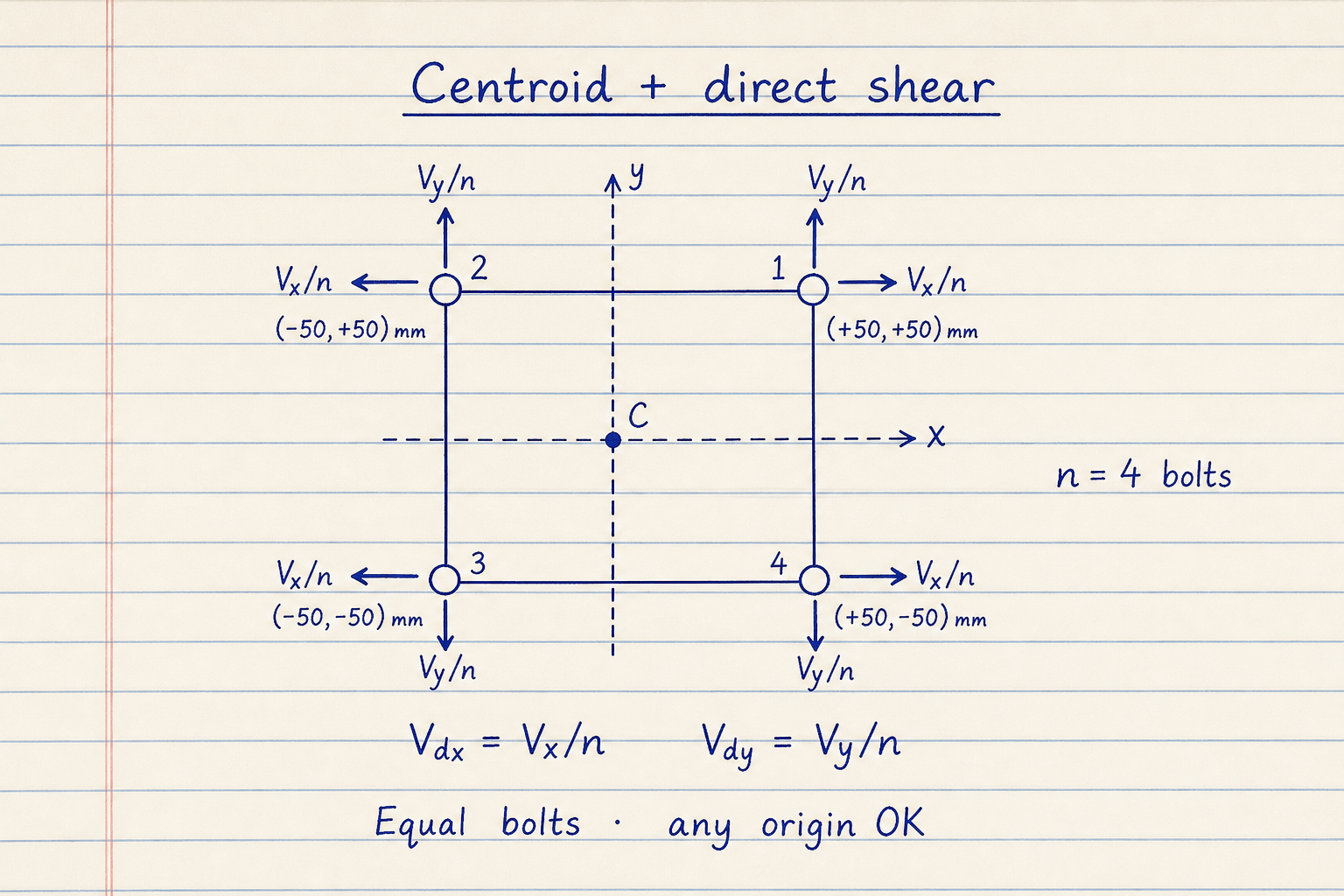
Equal bolts share direct shear as Vx/n and Vy/n.
Coordinates may use any origin; the pad recomputes C automatically.
Torsional shear from Mz uses polar J
In-plane moment resolution with unit-area polar moment J uses Vmx = Mz·y′/J and Vmy = −Mz·x′/J for CCW-positive Mz.
On the defaults, bolts at x = −50 mm pick up the largest resultant ≈ 2549.5 N. Bolts at x = +50 mm see ≈ 1581 N. The critical bolt is the max Vres; ties keep the lowest index.
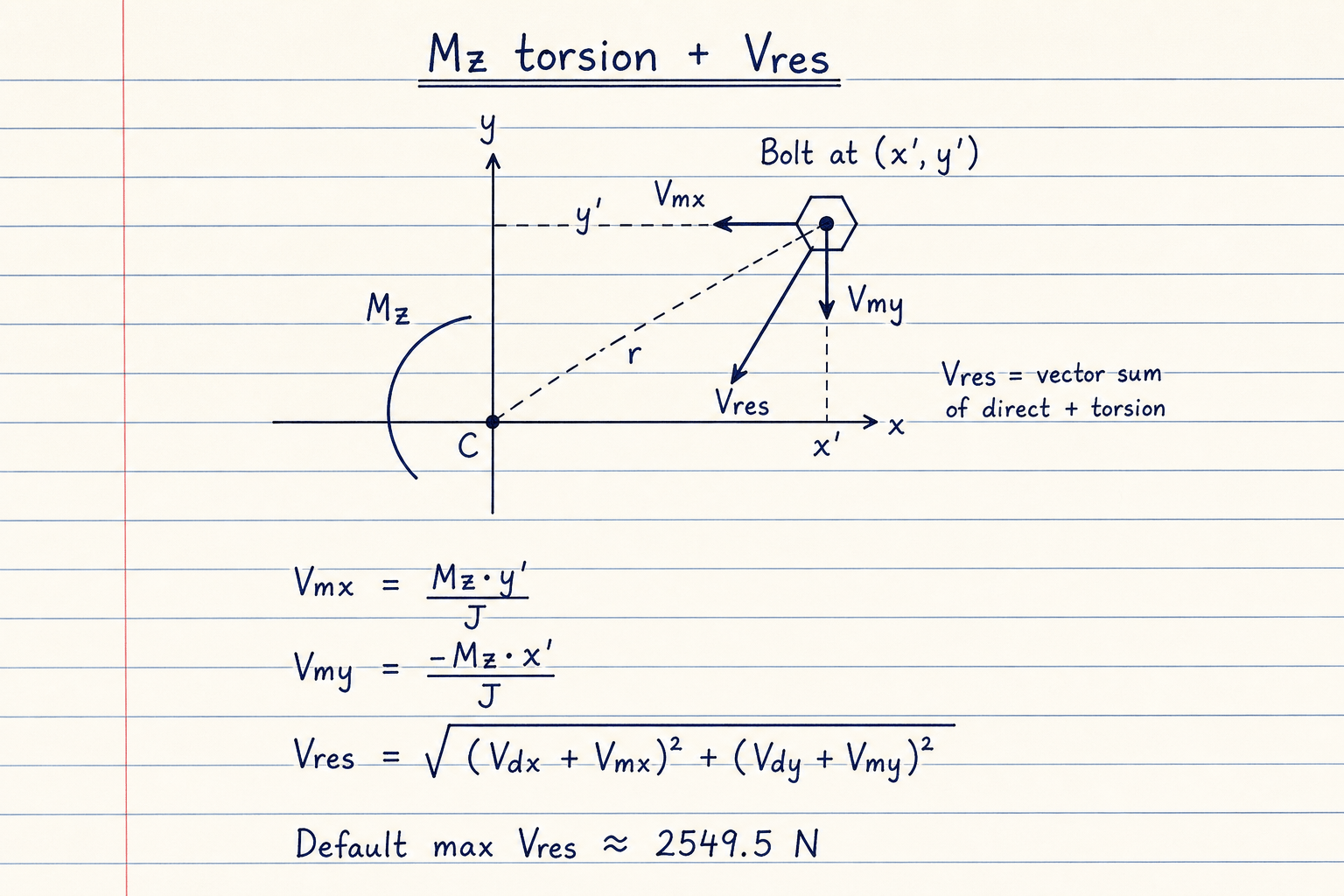
Mz = Vy·ex + Vx·ey + Mz,direct.
Vres combines direct and torsional components vectorially.
Pattern generators vs custom coordinates
Rectangular and circular generators save hand-entering coordinates. This pad does the same, plus custom X/Y up to 12 bolts.
Circular start angle 45° with radius √2×50 mm recreates the default square corners. Out-of-plane bending, AISC IC plastic method, and bearing/DCR checks are out of scope here; use a steel-connection worksheet for code capacity.
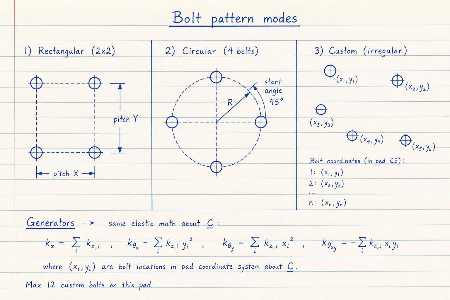
Rectangular: rows × columns with pitch X/Y centered on C.
Custom: any origin; centroid still computed from the entered points.
Worked example
Default Metric 2×2: pitch 100×100 mm, Vy = 8000 N, ex = 25 mm, Vx = ey = Mz = 0.
- Leave Rectangular grid 2×2. CALCULATE.
- Bolts at (±50, ±50) mm · C = (0, 0) · J = 20,000 mm².
- Mz = 8000 × 25 = 200,000 N·mm · Vdy = 2000 N.
- Critical bolts at x = −50 mm → Vres ≈ 2549.5 N.
- Far-side bolts at x = +50 mm → Vres ≈ 1581 N.
Result: Max Vres ≈ 2549.5 N; size fasteners against that shear (plus your code factors).
When to use
- Finding the most loaded bolt in a bracket or flange under eccentric shear
- Comparing rectangular vs circular bolt layouts for the same load
- Checking custom or irregular bolt coordinates before detailing
- Hand-check of elastic shear results before detailing
- First-pass force input before bolt strength or torque pads
Limitations
- In-plane elastic shear only. No out-of-plane axial from Mx/My bending.
- No Instantaneous Center (IC) / AISC plastic method.
- Equal bolts assumed (unit area). Mixed diameters need a weighted model.
- No shear capacity, bearing, or DCR checks; raw forces only.
- Max 12 custom bolts. Not a substitute for a sealed connection design.
FAQ
- Elastic or Instantaneous Center method?
- This pad uses the elastic (linear) method: conservative for many machine brackets. Plastic group methods exist for steel buildings when you need group capacity from code tables. We stay elastic and report forces only.
- How is Mz formed from eccentricity?
- Mz = Vy·ex + Vx·ey + any direct Mz you type. Positive Mz is counterclockwise about the pattern plane.
- Why are two bolts equally critical?
- On a symmetric 2×2 with pure Vy and ex, the two bolts on the side that adds torsion to direct shear share the same Vres. The pad highlights the lowest index among ties.
- What if J is zero?
- All bolts sit on the centroid (for example a single bolt at C). Direct shear still splits as V/n, but torsional shear is zero because there is no lever arm. The pad shows an amber note when Mz is nonzero and J = 0.
- Does this check bolt capacity?
- No. It returns shear force per bolt. Use the bolt strength calculator (or your AISC/Eurocode worksheet) for φRn, bearing, and interaction.
- What about prying and out-of-plane loads?
- Some bolt-group tools cover axial distribution from Mx/My separately. This pad is the in-plane eccentric shear case only. Prying and heel/toe bending need a joint model beyond these formulas.
Bolt / Fastener Strength Calculator
Bolt capacity for ISO metric, ANSI UNC, or ACME: As/At, proof/yield/ultimate, FoS, preload, estimated shear.
Open calculatorBolt Torque Calculator
Tightening torque from diameter, target preload, and lubrication K. Metric ISO or inch UNC, reverse clamp load, and % of proof.
Open calculatorWeld Joint Strength Calculator
Fillet and groove weld capacity for tee, lap, corner, edge, and butt joints — throat, stress, and factor of safety.
Open calculatorKey & Keyway Design Calculator
ANSI B17.1 / ISO 773 key lookup plus parallel-key shear and bearing stress check under torque.
Open calculator