You need a first-pass tightening torque before you set a wrench, compare dry vs oiled K, or reverse-check clamp load from a known torque. This pad uses the industry screening formula T = K × F × d with lubrication presets, metric size chips (M6–M36), optional custom K, and three modes: torque from clamp load, clamp load from torque, and suggest from property class (% of proof).
Defaults open on Torque from clamp load: M12, lightly oiled (K = 0.15), target 25 kN. CALCULATE returns T = 45 N·m (≈ 33.2 ft·lb). Switch to Clamp load from torque to rearrange F = T / (K × d), or Suggest from grade to set F from ISO coarse As × proof stress × % then torque. Math stays in your browser.
It sits under Mechanical Calculators next to the bolt strength calculator and safety factor calculator. This pad is a K-method screen, not a VDI 2230 joint design.
Formula
- Tightening torque: T = K × F × d. T in N·m, F in N, d in metres (d_mm ÷ 1000), K dimensionless.
- Reverse clamp load: F = T / (K × d). Reported here in kN.
- Proof load (metric coarse): F_proof ≈ As × Sp. As in mm², Sp in MPa → F_proof in N; divide by 1000 for kN.
- Grade mode preload: F = (% of proof / 100) × F_proof. Then T = K × F × d.
- ft·lb conversion: T_ft·lb = T_N·m × 0.737562.
- K from lubrication preset, or Custom K when override > 0 (lubrication is folded into K — do not also apply a separate lube % on top).
Reproduce the default Torque from clamp load path on CALCULATE:
| Quantity | Value |
|---|---|
| Size / diameter | M12 · 12 mm |
| Lubrication | Lightly oiled · K = 0.15 |
| Target clamp load F | 25 kN |
| Tightening torque T | 45 N·m (≈ 33.2 ft·lb) |
| Dry check (K = 0.20, same F) | 60 N·m |
How it works
Pick torque-from-clamp, clamp-from-torque, or suggest-from-grade. K comes from lubrication or a custom override. Grade mode uses ISO coarse tensile stress area and proof stress. Confirm final torque with the fastener supplier chart for critical joints.
Pick Input mode: Torque from clamp load (default), Clamp load from torque, or Suggest from grade (% proof). Choose a metric size (or Custom diameter), lubrication, optional Custom K, and property class (used for the % of proof result). Mode 0 needs clamp load in kN; mode 1 needs applied torque in N·m; mode 2 also needs % of proof and a metric size for As (switching into grade mode from Custom jumps to M12). CALCULATE fills Results and updates the live 3D K-factor sketch (Play/Pause on the diagram). Editing a field clears Results. RESET restores M12 oiled 25 kN defaults.
One K, not K plus a second lubrication percent
Some torque tools write T = K × F × d × (1 − l/100), where l is a separate lubrication reduction. That works when K is a dry material coefficient and l is an extra discount.
This pad follows the shop-chart style: each lubrication option already carries its own K (dry 0.20, oiled 0.15, moly 0.10, and so on). Enter Custom K only when a data sheet gives one number. Do not stack a separate lubrication percent on top of an already-lubricated K — you would under-torque.
K presets on this pad (lubrication folded in):
| Condition | K |
|---|---|
| Dry steel | 0.20 |
| Lightly oiled | 0.15 |
| Moly grease | 0.10 |
| Anti-seize | 0.12 |
| Hot-dip galvanized | 0.18 |
| Stainless on SS | 0.30 |
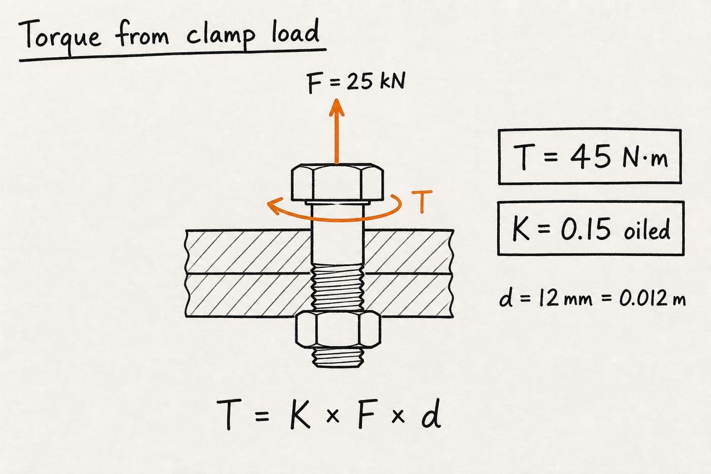
Default CALCULATE path: M12, K = 0.15, F = 25 kN → T = 0.15 × 25,000 × 0.012 = 45 N·m.
Switch lubrication to Dry steel (K = 0.20) on the same clamp load to see 60 N·m.
Reverse mode: clamp load from a fixed wrench setting
Many shop charts rearrange the same equation when torque is known and preload is the unknown. F = T / (K × d) answers “what clamp load does this wrench setting imply under my assumed K?”
On this pad, choose Clamp load from torque, keep M12 and K = 0.15, enter 45 N·m, and CALCULATE returns 25 kN. That is the inverse of the default forward path. Real preload still scatters with friction — treat the result as a K-method estimate, not a measured tension.
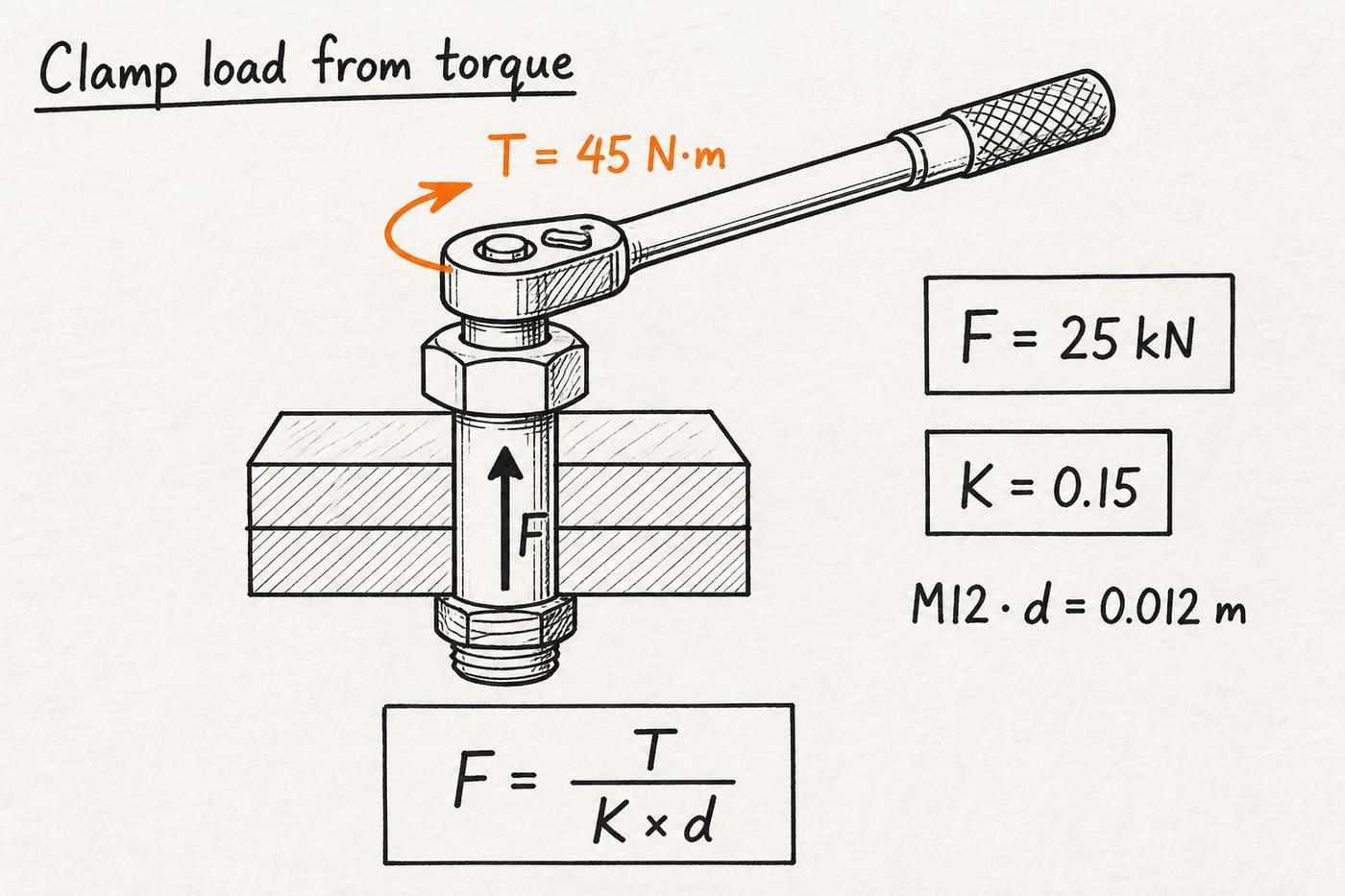
Reverse example: T = 45 N·m, K = 0.15, d = 0.012 m → F = 25 kN.
Use this when a drawing already lists a torque and you need an estimated preload for a joint check.
Grade mode uses proof load, not ultimate tensile as the target
Supplier charts emphasize material proof strength, size, and friction when estimating torque. Industry practice often targets about 70–75% of proof (sometimes quoted near 75% of proof or ~70% of UTS depending on the chart) for reusable joints.
Suggest from grade on this pad: pick M6–M36 (ISO coarse As), property class (4.6–12.9 with approximate Sp), and % of proof. Example: M12 · 8.8 · Sp ≈ 600 MPa · As = 84.3 mm² → proof ≈ 50.6 kN; at 75% and K = 0.15, F ≈ 37.9 kN and T ≈ 68.3 N·m. Custom diameter alone is not enough in grade mode — As must come from a metric size chip.
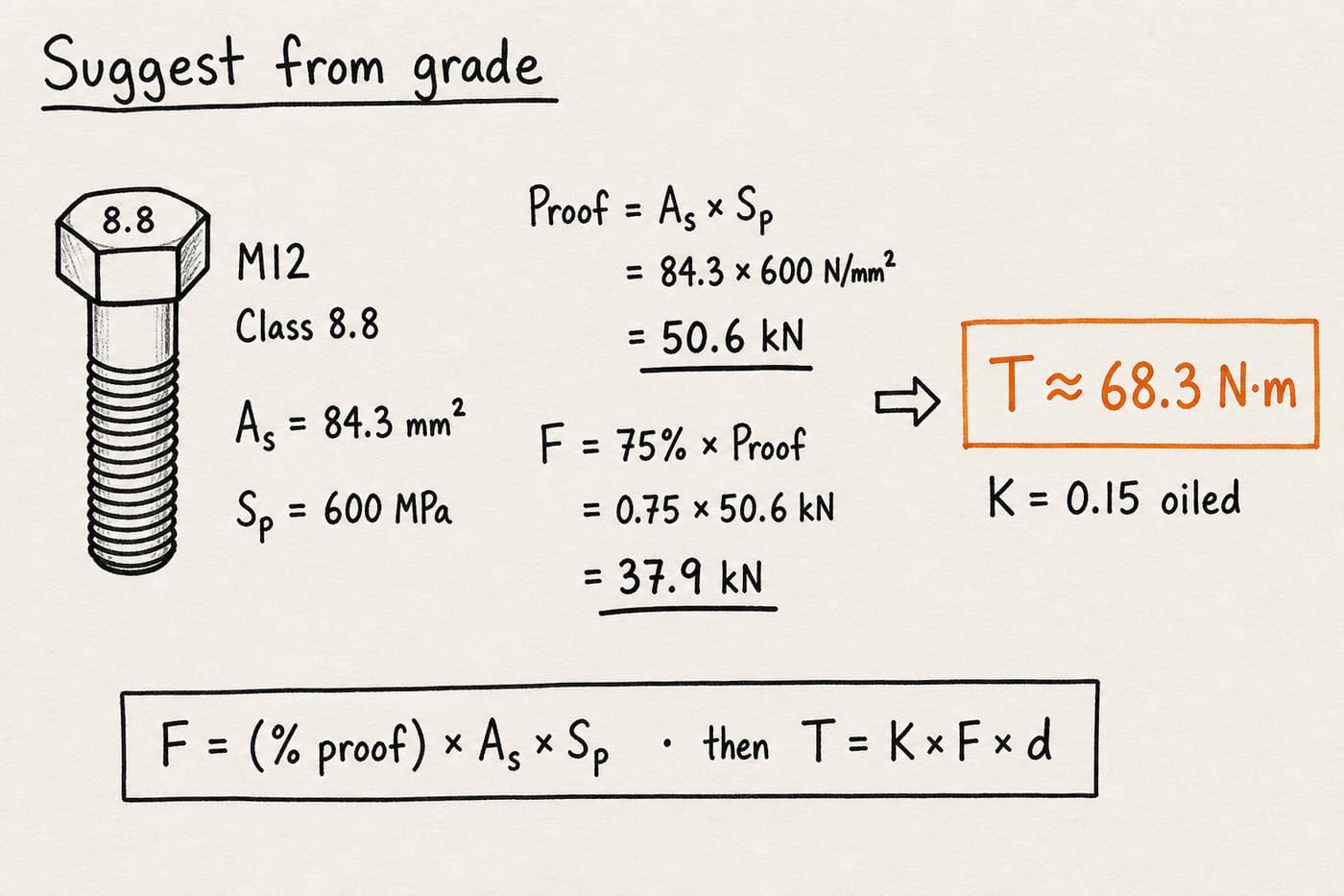
Grade path: proof = As × Sp, then F = (%/100) × proof, then T = K × F × d.
The pad warns when estimated preload exceeds 90% of proof — prefer ≤75–80% for reusable joints.
K-method scatter and when to leave this pad
Nut-factor torque is a screening tool. Friction scatter of ±25–30% is common once coatings, washers, thread condition, and under-head finish vary. Critical pressure boundaries, dynamic machine joints, and code flanges need the fastener manufacturer’s chart, torque-angle / stretch methods, or a VDI 2230-style detailed friction model.
This pad does not implement VDI 2230 (pitch, μ_t, μ_b, bearing diameter). It also does not check thread stripping, gasket relaxation, or joint separation. After you lock a first-pass T and F, continue with supplier data or a full joint analysis for safety-critical work.
Worked example
Default Torque from clamp load: M12, lightly oiled (K = 0.15), target clamp load 25 kN. Reproduce on CALCULATE.
- Leave Input mode on Torque from clamp load. Size M12, lubrication Lightly oiled, Custom K = 0, clamp load 25 kN.
- CALCULATE. F = 25,000 N, d = 0.012 m, K = 0.15 → T = 0.15 × 25,000 × 0.012 = 45 N·m (≈ 33.2 ft·lb).
- Dry check: set lubrication to Dry steel (K = 0.20), same F → T = 60 N·m.
- Reverse example: mode Clamp load from torque, 45 N·m, K = 0.15 → F = 25 kN.
- Grade example: Suggest from grade, M12, 8.8, 75% proof, K = 0.15 → proof ≈ 50.6 kN, F ≈ 37.9 kN, T ≈ 68.3 N·m.
Result: Default: 45 N·m. Dry same clamp: 60 N·m. Reverse 45 N·m → 25 kN. Grade M12 8.8 @ 75% oiled ≈ 68.3 N·m.
When to use
- Setting a first-pass torque wrench value from target clamp load
- Comparing dry vs oiled vs coated K before you open a supplier chart
- Estimating preload implied by an existing torque callout
- Suggesting torque from metric size, property class, and % of proof
- Quick screening when a full VDI 2230 analysis is not yet justified
Limitations
- K-factor method often has ±25–30% preload scatter in real joints.
- Single K folds lubrication in; not a separate material-K × lube-% product.
- Not a VDI 2230 detailed friction model (no pitch / μ_t / μ_b / D_km).
- Does not check thread stripping, bearing stress, gasket relaxation, or joint separation.
- Grade As values are ISO metric coarse on this pad; fine pitch and inch grades need supplier tables.
- Not a substitute for the fastener manufacturer’s assembly chart on critical joints.
FAQ
- What is the K factor in bolt torque?
- K is an empirical nut factor that lumps thread friction and under-head friction into one number. Typical dry steel is about 0.20; lightly oiled about 0.15. On this pad, lubrication presets set K directly.
- What formula does this calculator use?
- T = K × F × d with F in newtons and d in metres. Reverse mode uses F = T / (K × d). Grade mode sets F from % of proof × As × Sp, then applies the same torque formula.
- Why is my torque different from other online calculators?
- Some sites multiply by (1 − lubrication%/100) on top of a material K. This pad’s oiled/moly presets already include lubrication in K. Matching numbers means using the same K convention, not stacking both.
- How accurate is bolt torque from the K method?
- Often only within about ±25–30% on preload because friction varies. Use it for planning and comparison; verify critical joints with supplier charts, stretch, or ultrasonic tension.
- What percent of proof load should I use?
- Many reusable-joint charts aim near 70–75% of proof. This pad defaults to 75% in grade mode and warns above 90%. Follow the fastener standard or drawing note for your joint.
- When should I not use this calculator?
- Safety-critical joints, high dynamic load, gasketed pressure flanges under code, and any joint that requires VDI 2230 or a manufacturer torque-tension curve.
- Where do I check if the bolt can take my axial load?
- Use the bolt strength calculator for As, proof/yield/ultimate loads, and FoS vs applied tension. This pad is for wrench torque and preload from K.
Beam Stress and Deflection Calculator
Six textbook beam cases: max moment, shear, stress, deflection, slope, and L/360 check with animated 2D sketches.
Open calculatorPress Fit and Shrink Fit Calculator
Lamé contact pressure, hub/shaft stress, torque and press force, yield safety factors, and shrink ΔT for interference fits.
Open calculatorSafety Factor Calculator
Factor of safety from strength ÷ stress. Yield or ultimate basis, material presets, and reverse solve modes.
Open calculator