You need even pitch count, corrected center distance, and a first-pass tensile safety check for an ANSI roller chain drive, or a geometry-only check when teeth and spacing are already fixed. This pad does both. Mode 0 is power sizing: design power from P × Ks × Kl, z2 from the speed ratio, then length, wrap, chain speed, pull, and SF versus approximate breaking load. Mode 1 is geometry check: enter z1, z2, pitch (via chain size), and desired C.
Defaults open on the Shigley-style #40 case: 5 kW, 1450→480 rpm, z1=19, C=500 mm, Ks=1.4, Kl=1. CALCULATE returns design power 7 kW, z2=57, Lp=118 pitches, actual C≈502.1 mm, d1/d2≈77.16/230.54 mm, wrap≈162.4°, v≈5.83 m/s, and tensile SF≈11.7. Strand presets multiply approximate capacity (simplex ×1.0, duplex ×1.7, triplex ×2.5). Speed-up layouts (n1 < n2) keep z2 below z1 instead of forcing 17 teeth. Math stays in your browser.
It sits under Mechanical Calculators next to the belt drive calculator and gear ratio calculator. Manufacturer configurators still own final series, lubrication system, and guarding.
Formula
- Design power: P_design = P × Ks × Kl (power mode).
- Speed ratio: i = n1/n2 (power mode) or i = z2/z1 (geometry mode).
- Chain length (pitches): Lp = 2(C/p) + (z1+z2)/2 + (z2−z1)²/(4π²(C/p)); round UP to even.
- Actual center distance from even Lp: A=(z2−z1)/(2π), B=Lp−(z1+z2)/2, C=(p/4)(B+√(B²−8A²)).
- Pitch diameter: d = p / sin(π/z) — not the large-z approximation z·p/π.
- Wrap (small sprocket): 180° − 2·arcsin(|d2−d1|/(2C)); target ≥ 120°.
- Chain speed: v = z1·p·n1/60000 (m/s). Pull F = P_design·1000/v (N).
- Tensile SF = (Fb·strandFactor·1000)/F; band: <7 fail, 7–10 marginal, ≥10 comfortable.
Reproduce the default Power sizing path on CALCULATE (#40 · 5 kW · 1450→480):
| Quantity | Value |
|---|---|
| Inputs | #40 · 5 kW · 1450/480 rpm · z1=19 · C=500 · Ks=1.4 |
| Design power | 7 kW |
| z2 / Lp / actual C | 57 · 118 pitches · ≈ 502.1 mm |
| d1 / d2 / wrap | ≈ 77.16 / 230.54 mm · ≈ 162.4° |
| v / pull / SF | ≈ 5.83 m/s · ≈ 1200 N · ≈ 11.7 |
How it works
Two modes: power sizing with service and lubrication factors, or geometry-only from z1, z2, and center distance. Pitch diameter uses p/sin(π/z). Chain length rounds up to even pitches, then center distance is recalculated. Safety factor compares breaking load to chain pull.
Pick Input mode: Power sizing (default) or Geometry check. Choose ANSI size and strand count, or a Quick preset (Shigley #40, geometry 19/57, light #35). Enter fields for that mode, then CALCULATE. Results update the live sprocket sketch (Play/Pause). Editing a field clears Results. RESET restores the #40 · 5 kW · C=500 defaults.
Even pitches first, then the center distance you can build
The ANSI length equation is solved first, then an even link count is forced so you can close the loop with a standard master link.
This pad rounds UP to the next even pitch count (not down), then inverts for actual C. That matches shop practice: never order an odd count that needs a half-link unless you accept the fatigue knock. Ideal C is often about 30–50× pitch; wrap on the small sprocket should stay at or above 120°.
Default geometry example (#40, z1=19, z2=57, C_desired=500 mm):
| Step | Result |
|---|---|
| C/p | ≈ 39.37 |
| Lp raw | ≈ 117.67 |
| Lp even | 118 |
| Actual C | ≈ 502.1 mm |
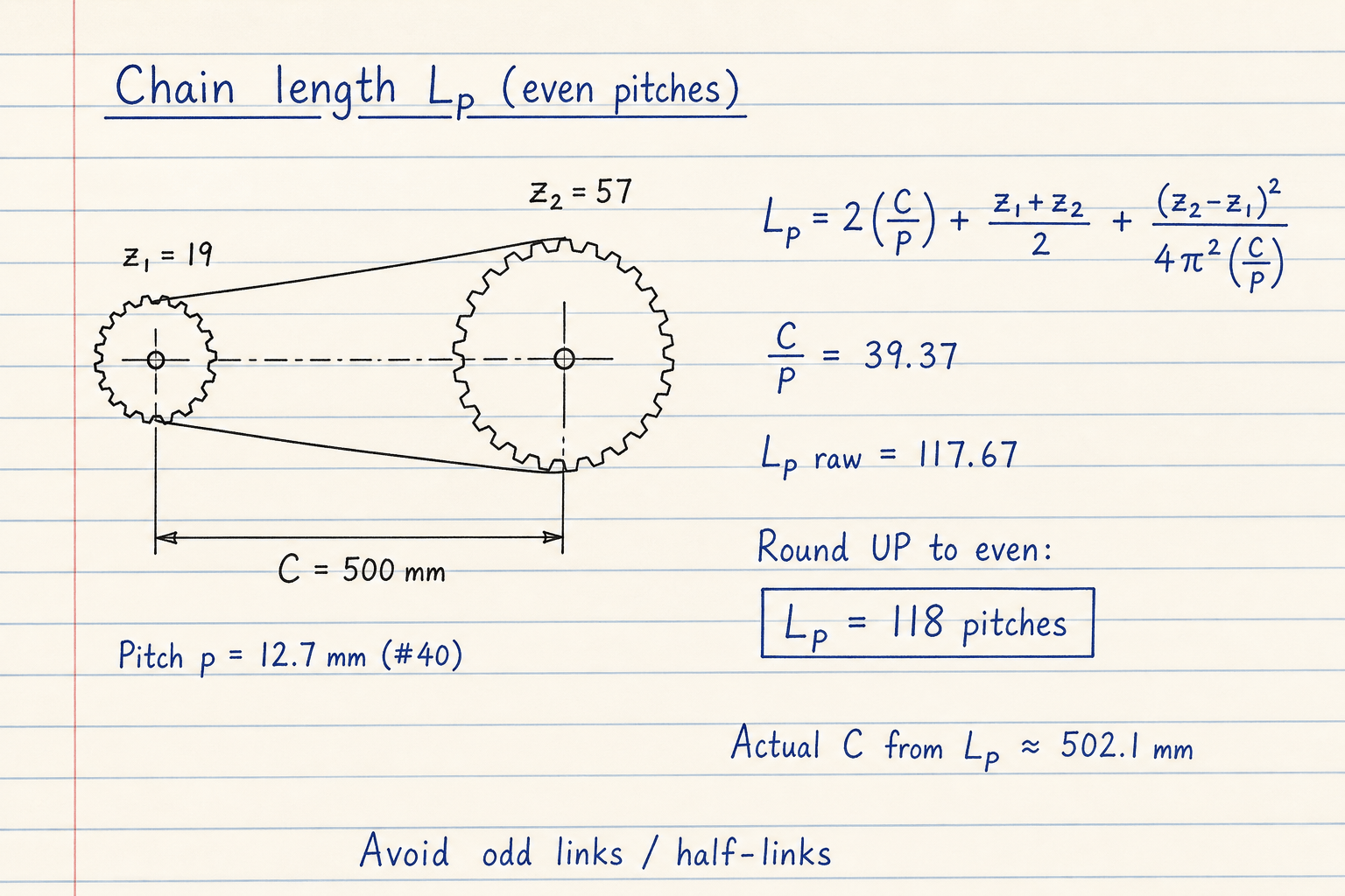
Default CALCULATE path: Lp raw ≈ 117.67 → 118 even pitches; actual C ≈ 502.1 mm.
Order an even pitch chain; adjust take-up a few millimetres rather than removing one link.
Pitch diameter is p / sin(π/z), not z·p/π
Many quick sketches use d ≈ z·p/π. That is only fair for large tooth counts. ANSI / ISO sprocket pitch diameter is the polygon formula d = p / sin(π/z). For #40 at z1=19 that is 77.16 mm, not 76.8 mm from the circle approximation — and wrap angle uses those diameters.
Handbooks publish the sin form. This pad uses it for d1, d2, and wrap. If your old spreadsheet still uses z·p/π, wrap and clearance checks will drift on small sprockets where chordal action already matters most.
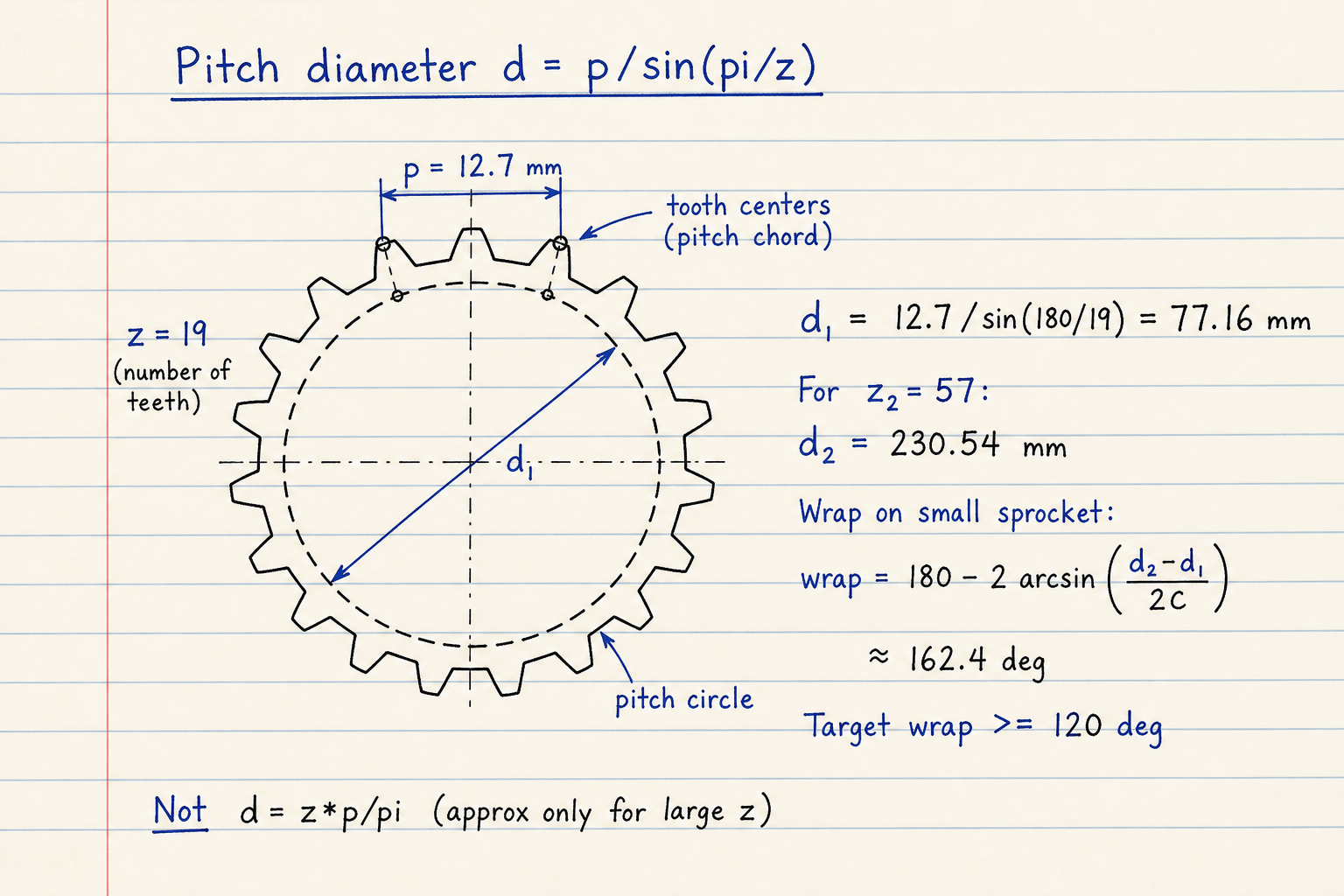
Default #40 · z1=19 → d1 ≈ 77.16 mm; z2=57 → d2 ≈ 230.54 mm.
Wrap ≈ 162.4° on the small sprocket for the default C — above the 120° target.
Power path: design kW, pull, SF, and approximate capacity
Chain selection starts from design power P×Ks×Kl, then screens a chain number. Textbooks (Shigley) follow the same path. Pitch can also be sized from torque and multi-row factors. OEM catalog tools remain the authority for final product selection.
Here, tensile SF compares approximate breaking load (× strand factor) to chain pull from design power and speed. Separately, an approximate Pr table screens whether the selected ANSI size looks under capacity at ~1000 rpm basis. Those Pr / Fb rows are prompts — confirm against the current manufacturer catalog for your rpm, teeth, and duty. Duplex ≈ ×1.7 and triplex ≈ ×2.5 are common strand multipliers, not guarantees.
Default power example (simplex #40):
| Quantity | Value |
|---|---|
| P_design | 5 × 1.4 × 1 = 7 kW |
| v | ≈ 5.83 m/s |
| Pull | ≈ 1200 N |
| Fb / SF | ≈ 14.1 kN · SF ≈ 11.7 (comfortable) |
| Pr screen | #40 Pr≈2.2 kW < 7 → consider larger pitch or more strands |
What this pad is not
Not a silent-chain or belt calculator. Not wear elongation, alignment tolerance, or LOTO / guard design. Not a manufacturer Product Select that returns a SKU. For ratio-only tooth checks use the gear ratio pad; for V-belt length and belt count use the belt drive pad.
Scope boundaries:
| In scope | Out of scope |
|---|---|
| Even Lp + actual C | Half-link / offset-link detailing |
| d = p/sin(π/z) + wrap | Silent chain / toothed belt |
| P×Ks×Kl + tensile SF | OEM catalog life / horsepower tables |
| Strand ×1.0 / 1.7 / 2.5 prompts | Guarding, LOTO, lubrication system design |
Worked example
Default Power sizing: ANSI #40, 5 kW, 1450→480 rpm, z1=19, C=500 mm, Ks=1.4, Kl=1, simplex. Reproduce on CALCULATE.
- Leave Quick preset on Shigley #40 · 5 kW · 1450→480 (or enter the same values). Mode = Power sizing.
- CALCULATE → design power 7 kW; z2=57; Lp=118; actual C≈502.1 mm.
- Check pitch diameters ≈ 77.16 / 230.54 mm and wrap ≈ 162.4° (≥ 120°).
- Chain speed ≈ 5.83 m/s; pull ≈ 1200 N; tensile SF ≈ 11.7 (comfortable).
- Geometry example: switch to Geometry check with z1=19, z2=57, #40, C=500 → same Lp and C.
- Note: approximate Pr for #40 is below 7 kW — the pad may suggest a larger size for capacity screening even when tensile SF is fine. Confirm with the catalog.
Result: Default: Lp=118, C≈502.1 mm, wrap≈162.4°, SF≈11.7. Capacity screen may recommend upsizing pitch vs the approximate Pr table.
When to use
- Ordering roller chain by even pitch count and buildable center distance
- First-pass ANSI size and strand screen from power and rpm
- Checking wrap angle and C/p band before freezing shaft spacing
- Comparing geometry-only layouts (z1/z2/C) without re-entering power
- Cross-checking spreadsheet pitch diameter (sin form vs z·p/π)
Limitations
- ANSI roller chain only — not silent chain, leaf chain, or belt.
- Pr and Fb rows are approximate screening values, not current manufacturer ratings.
- Strand factors (1.0 / 1.7 / 2.5) are common prompts; series and duty can differ.
- Does not compute wear elongation, chordal vibration spectrum, or lubrication interval.
- Does not design guards, take-up hardware, or LOTO procedures.
- OEM chain selectors remain the authority for product selection.
- Single-stage ratios above about 7:1 usually need a jackshaft — not modeled here.
FAQ
- Why is chain length always an even number of pitches?
- Roller chain alternates inner and outer links. An even pitch count closes with a standard master link. Odd counts need an offset half-link that cuts fatigue strength — this pad rounds up to even instead.
- What safety factor should I target?
- Many industrial drives aim for tensile SF of 7–10 or higher from breaking load over working pull. This pad flags below 7 as fail and 7–10 as marginal. Shock, starts, and environment still belong in Ks and the catalog.
- Why recommend a larger chain when SF looks fine?
- Tensile SF from breaking load is not the same as horsepower capacity. Approximate Pr tables (speed- and teeth-dependent) can call for a larger pitch even when SF > 10. Treat the recommend row as a catalog prompt.
- How many teeth on the small sprocket?
- ANSI practice prefers at least 17 teeth (19–21 better) on high-speed drivers to limit polygonal / chordal action. The pad warns below 17 but still computes so you can inspect slow or space-limited layouts.
- What center distance should I use?
- A common rule is C ≈ 30–50× pitch with wrap ≥ 120° on the small sprocket. After even Lp, use the actual C and leave take-up for sag (about 2–3% of C on horizontal drives).
Belt Drive Calculator
Classical, narrow, cogged, flat, timing, and poly-V belt sizing plus open/crossed length and C from L.
Open calculatorGear Ratio Calculator
Gear ratio, output RPM, and torque for spur pairs, compound trains, direct ratio, speed solve, or idler trains.
Open calculatorMotor Gearbox Selector Calculator
Motor power from load torque, or gearbox output torque from motor power, ratio, SF, and efficiency.
Open calculator