You need the first critical whirling speed of a rotating shaft or screw so operating RPM stays clear of resonance. This pad has three modes. Static deflection (Rayleigh) turns a known midspan sag into Nc. Shaft geometry builds stiffness from EI and support type, then Nc from √(k/m) or a uniform simply-supported Euler beam. Screw / end-fixity uses the catalog fc·(d/L²)·10⁷ screen common on ball-screw manufacturer notes.
Defaults open on Static deflection: δ = 0.5 mm, operating 1000 rpm, 25% separation target. CALCULATE returns Nc ≈ 1338 rpm, fn ≈ 22.3 Hz, ratio ≈ 0.75, and a clear margin with a 0.8×Nc subcritical screen ≈ 1070 rpm. Switch to the pump-shaft preset (Ø50×800 mm, 30 kg, 3000 rpm) or the Ø20×1000 mm fixed-supported screw preset for geometry and end-fixity examples. Math stays in your browser.
It sits under Mechanical Calculators next to the vibration natural frequency calculator and shaft design calculator. Automotive driveshaft SKU tables and athletic “critical speed” (running physiology) are out of scope.
Formula
- Rayleigh: Nc (rpm) = (60/2π)·√(g/δ) with δ in meters, g = 9.81 m/s².
- Imperial example: Nc ≈ 187.7 / √δ_in (same physics).
- Geometry: I = πd⁴/64 (solid) or π(OD⁴−ID⁴)/64; SS center k = 48EI/L³; fixed-fixed center k = 192EI/L³; cantilever k = 3EI/L³; ωn = √(k/m); Nc = ωn·60/(2π).
- Uniform SS shaft: ω = (π/L)²√(EI/μ) with μ = ρA (Steel / Stainless / Aluminum density presets only).
- Screw / end-fixity (metric): nc = fc·(d/L²)·10⁷; fc = 3.4 / 9.7 / 15.1 / 21.9.
- Subcritical screen: N_safe ≈ 0.8·Nc. Ratio r = Nop/Nc; danger near 0.9–1.1; caution inside separation target or 0.8–1.2.
Reproduce the default Static deflection path on CALCULATE:
| Quantity | Value |
|---|---|
| Inputs | δ = 0.5 mm · Nop = 1000 rpm · sep 25% |
| Nc / fn | ≈ 1338 rpm · ≈ 22.3 Hz |
| Ratio r | ≈ 0.75 |
| 0.8 × Nc screen | ≈ 1070 rpm |
| Status | Clear of critical band |
How it works
Three modes: Rayleigh Nc from known static deflection, shaft geometry (solid/hollow + support stiffness), or screw/shaft end-fixity fc·d/L². Compares operating RPM to Nc with separation and a 0.8×Nc subcritical screen.
Pick Input mode: Static deflection (default), Shaft geometry, or Screw / end-fixity. Or use a Quick preset (static sag, pump shaft, screw). Enter fields for that mode, set operating RPM and separation target, then CALCULATE. Results update the live whirling sketch (Play/Pause). Editing a field clears Results. RESET restores δ = 0.5 mm / 1000 rpm.
Start from sag when you already have deflection
Shaft critical speed from static sag opens with the practical estimate Nc ≈ 187.7/√δ_in, which is exactly (60/2π)√(g/δ) in inch units. Mixer and agitator notes use the metric form from midspan or cantilever sag.
On this pad, mode 0 is that path. Measure or compute static deflection under the rotating weight, enter it in millimeters, and CALCULATE. Less sag means higher Nc. It is not a torque or horsepower limit. A shaft can be strong in shear and still whirl if it is soft laterally.
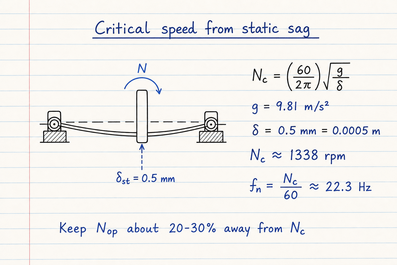
Default CALCULATE path: δ = 0.5 mm → Nc ≈ 1338 rpm, fn ≈ 22.3 Hz.
At 1000 rpm the ratio is ≈ 0.75, clear of the ±10% danger band and just outside a 25% separation window on the safe side.
Geometry mode when you know diameter, span, and mass
When sag is unknown, build bending stiffness from EI and the support case. Simply supported center load uses k = 48EI/L³. Fixed-fixed center uses 192EI/L³. Cantilever (overhung mixer / impeller) uses 3EI/L³. Then ωn = √(k/m) and Nc = fn×60. Hollow tubes use I = π(OD⁴−ID⁴)/64. Rotor mass (kg) wins if you also enter a tip/center load (N).
The pump-shaft preset mirrors a common example: Ø50 mm × 800 mm span, 30 kg center mass, steel, simply supported → Nc ≈ 4285 rpm. At 3000 rpm the ratio is ≈ 0.70. Uniform simply-supported shaft mode drops the concentrated mass and uses the Euler distributed-mass formula instead. Custom E has no density preset, so uniform self-mass and blank-mass density fallback are blocked until you enter mass or pick Steel / Stainless / Aluminum.
Pump-shaft geometry example (SS center, steel):
| Quantity | Value |
|---|---|
| L / d / m | 800 mm · 50 mm · 30 kg |
| I | ≈ 3.068×10⁻⁷ m⁴ |
| k | ≈ 6.04×10⁶ N/m |
| Nc | ≈ 4285 rpm |
| r at 3000 rpm | ≈ 0.70 (clear) |
Screw end-fixity: fc changes Nc by more than 6×
Ball and lead screw catalogs size from root diameter, unsupported length, and end fixity. Metric catalogs commonly write nc = fc·(d/L²)·10⁷ with fc = 3.4 / 9.7 / 15.1 / 21.9. Operate at or below about 80% of that Nc.
Mode 2 on this pad is that screen. The screw preset (d = 20 mm, L = 1000 mm, fixed-supported) returns Nc = 3020 rpm and a safe screen of 2416 rpm. Use root/minor diameter for screws, not the nominal major diameter. Automotive driveshaft product selectors are a different job (out of scope here).
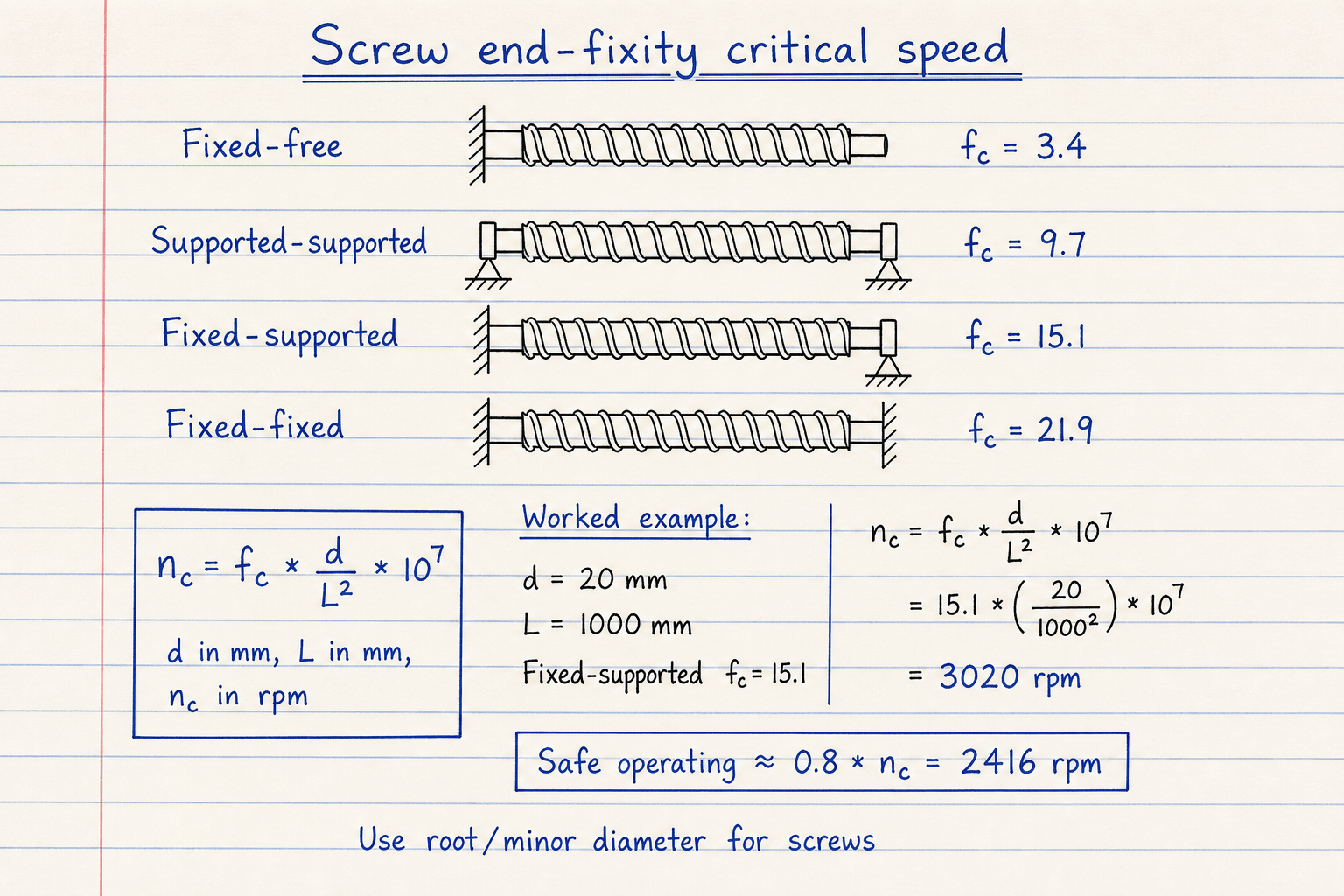
Fixed-supported fc = 15.1 · d = 20 mm · L = 1000 mm → nc = 3020 rpm.
Safe subcritical screen ≈ 0.8 × nc = 2416 rpm.
What this pad is not
Not automotive driveshaft product select. Not athletic critical speed physiology calculators. Not API rotordynamics with bearing stiffness maps, multi-mode FEA, or damping. For fn from a coil spring alone, use the vibration pad. For diameter from torque, use shaft diameter / shaft design.
Scope boundaries:
| In scope | Out of scope |
|---|---|
| Rayleigh Nc from δ | Athletic critical speed |
| EI geometry + support cases | Automotive driveshaft SKU tables |
| Screw fc · d/L² screen | API bearing-stiffness rotordynamics |
| Nop vs Nc margin + 0.8×Nc | Full multi-disc Dunkerley FEA |
Worked example
Default Static deflection: δ = 0.5 mm, operating 1000 rpm, 25% separation. Reproduce on CALCULATE.
- Leave Quick preset on Static sag · δ 0.5 mm · 1000 rpm (or enter the same values).
- CALCULATE → Nc ≈ 1338 rpm, fn ≈ 22.3 Hz, r ≈ 0.75, status Clear, 0.8×Nc ≈ 1070 rpm.
- Geometry example: Pump shaft preset → Nc ≈ 4285 rpm at 3000 rpm (r ≈ 0.70).
- Screw example: Ø20 × 1000 mm fixed-supported → Nc = 3020 rpm, safe ≈ 2416 rpm.
- Imperial check of the default sag: δ = 0.5 mm = 0.01969 in → 187.7/√δ ≈ 1338 rpm (matches).
Result: Default: Nc ≈ 1338 rpm, clear at 1000 rpm. Geometry pump shaft ≈ 4285 rpm. Screw fixed-supported 3020 rpm (safe 2416).
When to use
- Screening first critical speed from measured or calculated static sag
- Checking pump, fan, or mixer shafts from diameter, span, and rotor mass
- Ball / lead screw speed limits from root diameter and end fixity
- Comparing operating RPM to Nc with a separation target before VFD commissioning
- Cross-checking the vibration pad’s Nc = fn×60 when you only have δ
Limitations
- First-mode estimate only. Not higher whirling modes or coupled bending-torsion.
- Rigid bearings assumed; soft pedestals lower real Nc.
- Screw fc table is a steel catalog approximation. Confirm with the screw maker.
- Does not select driveshaft tube series, u-joint angles, or balance RPM limits.
- Not athletic critical speed physiology calculators.
- Not a substitute for API rotordynamics or FEA on critical machinery.
- Uniform-shaft mode ignores concentrated discs. Add mass in the center-load case when a rotor dominates.
- Custom E has no density preset. Uniform self-mass and blank-mass density fallback require Steel / Stainless / Aluminum, or enter mass/load.
FAQ
- What separation from critical speed should I use?
- Many machine-design notes start at 20–30% away from Nc. Ball-screw makers often cap continuous speed at 80% of calculated Nc. This pad defaults to a 25% target and always shows the 0.8×Nc subcritical screen. Precision or lightly damped systems may need more margin.
- Why show 1/2 critical speed?
- Driveline guides warn that cardan u-joints can excite a twice-per-revolution vibration near half the true critical speed. The value is a cue for driveline work, not a second natural frequency of the shaft model.
- Static deflection vs geometry: which mode?
- Use Static deflection when you already know midspan sag (hand calc, FEA, or measurement). Use Shaft geometry when you know L, d, support type, and mass. Use Screw / end-fixity for ball or lead screws sized by catalog fc factors.
- Is athletic critical speed the same thing?
- No. Athletic critical-speed calculators are running physiology tools. This pad is mechanical shaft and screw whirling only.
- How does this relate to the vibration calculator?
- The vibration pad solves SDOF fn from k, m, δ, or pendulum length, then Nc = fn×60. This pad focuses on shaft/screw whirling paths (geometry, end fixity, and Rayleigh sag) with the same Nc definition when δ is known.
Vibration Natural Frequency Calculator
SDOF natural frequency from spring-mass, static sag, or pendulum, with damping and resonance check.
Open calculatorShaft Design Calculator
Minimum shaft diameter from torsion, bending, Guest/Rankine combined, ASME Km/Kt, or twist limit. Solid or hollow.
Open calculatorShaft Diameter Calculator
Quick solid or hollow shaft diameter from power/RPM or torque under pure torsion, with stock size and keyway option.
Open calculator