Storage · KE at speed
- Moment of inertia I
- —
- Angular speed ω
- —
- Stored energy E
- —
- Tip / surface speed
- —
- Energy density
- —
- Hoop stress (rim)
- —
- Status
- —
You need stored rotational energy from a spinning rotor, a punch-press or engine speed-fluctuation check, or a first material-limited energy-density screen. This pad does all three. Mode 0 is stored KE: inertia from geometry shape factor k_I, then E = ½Iω² with tip speed and an optional rim hoop-stress safety factor. Mode 1 keeps the classic machine-design path: ΔE between N1 and N2 plus coefficient of speed fluctuation Cs. Mode 2 is the stress limit: specific energy e = k_e·σ/ρ.
Defaults open on storage: solid disk k_I = 0.5, m = 50 kg, r = 0.3 m, N = 3000 rpm, steel stress screen on. CALCULATE returns I = 2.25 kg·m², E ≈ 111 kJ (≈ 30.8 Wh), tip ≈ 94 m/s, rim hoop ≈ 70 MPa, and SF ≈ 5.7. Quick presets also cover the legacy 300→280 rpm fluctuation example (ΔE ≈ 143 J, Cs ≈ 0.069), a thin-rim example, and a steel specific-energy screen. Math stays in your browser.
It sits under Mechanical Calculators next to the critical speed calculator and shaft design calculator. Use the critical speed and shaft design calculators for whirling and diameter checks.
Formula
- Inertia: I = k_I · m · r². Annular disk: I = ½ m (ri² + ro²) → k_I = ½(1 + (ri/ro)²).
- Common k_I: solid disk 0.5 · thin ring / rim 1.0 · solid sphere 0.4.
- Stored energy: ω = 2πN/60; E = ½ I ω²; tip speed = ω · r.
- Rim hoop-stress screen: σ ≈ ρ ω² r²; SF = σ_allow / σ.
- Fluctuation: ΔE = ½ I (ω1² − ω2²); Cs = |N1 − N2| / N_mean.
- Material limit: e = k_e · σ / ρ; E_max = e · m. k_e ≠ inertia k_I (flat-disk k_e ≈ 0.606 = 2/(3+ν)).
Default storage example (Mode 0 · solid disk · 3000 rpm):
| Step | Result |
|---|---|
| I = k_I m r² | 0.5 × 50 × 0.3² = 2.25 kg·m² |
| ω | 2π × 3000 / 60 ≈ 314.16 rad/s |
| E = ½ I ω² | ≈ 111 033 J ≈ 30.84 Wh |
| Tip speed | ω r ≈ 94.25 m/s |
| Steel rim screen | σ ≈ 69.7 MPa · SF ≈ 5.7 |
How it works
Three modes: stored energy E = ½ I ω² from inertia shape k_I, mass, and RPM; machine-design speed fluctuation ΔE and Cs between N1 and N2; and material-limited specific energy e = k_e·σ/ρ. Inertia k_I is not the same as stress mass-efficiency k_e. Optional rim hoop stress uses σ = ρ ω² r².
Pick a Quick preset or Mode. Storage needs geometry, mass, outer radius, and RPM; annular disks also need inner radius. Fluctuation needs N1 and N2. Material mode needs mass-efficiency k_e and a material (or Custom ρ/σ). Optional material on Modes 0/1 screens rim hoop stress — Custom ρ/σ fields appear only when you pick Custom. Results stay dashed until CALCULATE. Play/Pause controls the spinning sketch. RESET restores the solid-disk 3000 rpm storage defaults.
Stored energy scales with ω²
Flywheel energy tools start from E = ½ I ω². Doubling RPM quadruples stored energy, which is why high-speed composite rotors win on Wh/kg even when steel wins on cheap mass.
This pad’s Mode 0 follows that path with honest geometry presets. Solid disk uses k_I = 0.5. Thin rim uses k_I = 1.0. Annular disks compute I = ½ m (ri² + ro²). Tip / surface speed is always shown; optional material adds the rim hoop-stress screen σ = ρ ω² r² with SF against allowable tensile strength.
Default storage example:
| Quantity | Value |
|---|---|
| I | 2.25 kg·m² |
| E | ≈ 111 kJ · ≈ 30.8 Wh |
| Tip / steel SF | ≈ 94.2 m/s · SF ≈ 5.7 |
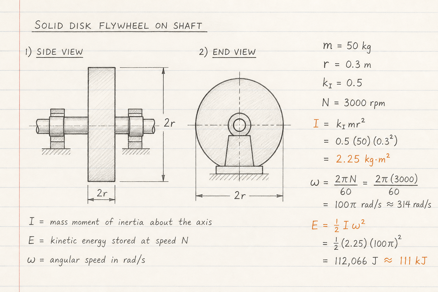
Default CALCULATE path: I = 2.25 kg·m², E ≈ 111 kJ at 3000 rpm.
Leave Material on None if you only need KE; turn Steel/Al/Composite on when tip speed starts to look aggressive.
Speed fluctuation for machine design
Punch presses and reciprocating engines care about energy exchanged between two speeds, not only peak KE. The work between ω1 and ω2 is ½ I (ω1² − ω2²). Mode 1 keeps TaskJunction’s original example: solid disk, 50 kg, 0.3 m, 300 → 280 rpm → ΔE ≈ 143 J and Cs ≈ 0.069.
Cs = (N1 − N2) / N_mean is the coefficient of speed fluctuation. Lower Cs means a smoother machine for the same mean speed — usually a larger I or a smaller energy demand per cycle.
Legacy fluctuation example (Mode 1):
| Quantity | Value |
|---|---|
| I | 2.25 kg·m² |
| KE(N1) / KE(N2) | ≈ 1110 J / ≈ 967 J |
| ΔE / Cs | ≈ 143 J / ≈ 0.069 |
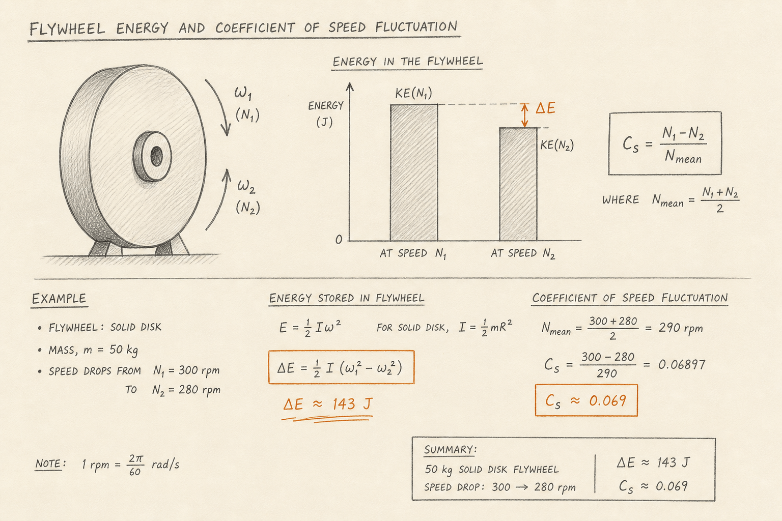
Use Mode 1 when the job is sizing I for a known cycle energy and an allowed speed band.
Full shaft-plus-disk inertia from density and thickness stays out of scope — enter an equivalent k_I or measured I via custom k_I.
k_I is not k_e
Flat-disk references also quote a geometric factor near 0.606. That number is mass-efficiency k_e = 2/(3+ν) for stress-limited specific energy e = k_e·σ/ρ — not the inertia shape factor k_I = 0.5 for a solid disk. Mixing them silently is a common confusion.
Mode 2 on this pad is only the material screen: pick k_e (thin ring 0.5, flat disk 0.606, bicone ≈ 0.95, ideal 1.0), density, and allowable strength. It answers “how many J/kg could this material store at the stress limit?” — not “what is I at this RPM?”
Worked example
Default storage: solid disk k_I = 0.5, m = 50 kg, r = 0.3 m, N = 3000 rpm. Reproduce on CALCULATE.
- Leave Quick preset on Storage · solid disk 50 kg · 3000 rpm (or enter the same values).
- CALCULATE → I = 2.25 kg·m²; ω ≈ 314.16 rad/s; E ≈ 111 033 J; tip ≈ 94.25 m/s.
- Fluctuation example: preset Fluctuation · 300 → 280 rpm → ΔE ≈ 143 J, Cs ≈ 0.069.
- Annular check: shape Annular, ri = 0.15 m, same m/r/N → k_I = 0.625, I = 2.8125 kg·m².
- Material example: Mode Material · steel · k_e 0.5 → e ≈ 25 478 J/kg ≈ 7.08 Wh/kg; E_max ≈ 1.27 MJ at 50 kg.
Result: Default storage ≈ 111 kJ. Legacy fluctuation ΔE ≈ 143 J. Material steel screen ≈ 7.08 Wh/kg.
When to use
- Estimating stored flywheel energy from mass, radius, shape, and RPM
- Sizing inertia to limit speed variation on presses and engines
- Comparing solid disk vs rim vs annular inertia for the same mass
- Screening rim hoop stress and tip speed before a detailed rotor study
- First-pass material-limited specific energy (Wh/kg) from σ and ρ
Limitations
- Inertia k_I and stress mass-efficiency k_e are different constants — do not swap them.
- Hoop stress uses a rim / thin-ring screen σ = ρ ω² r²; real disks have radial and tangential stress fields.
- Does not model bearing, windage, or vacuum enclosure losses.
- Does not size burst containment or composite layups.
- Does not build I from density × thickness × (ro⁴ − ri⁴) shaft-disk geometry.
- Assumes rigid-body rotation about a fixed central axis.
FAQ
- What is the difference between k_I and k_e?
- k_I sets inertia: I = k_I·m·r² (0.5 solid disk, 1.0 thin ring). k_e sets stress-limited specific energy: e = k_e·σ/ρ (≈ 0.606 for a flat disk with ν ≈ 0.3). This pad keeps them in separate modes.
- What is the speed fluctuation coefficient?
- Cs = |N1 − N2| / N_mean. It compares speed swing to mean speed (always ≥ 0). Lower Cs means smoother operation for the same mean RPM. ΔE stays signed so you can see which speed is higher.
- Solid disk vs thin ring?
- A uniform solid disk uses k_I = 0.5. A thin ring with mass at the rim uses k_I = 1.0, so it stores twice the energy for the same mass, outer radius, and RPM — until tip-speed / hoop-stress limits intervene.
- When should I use Material mode?
- When you care about the best-case Wh/kg a material can reach at its tensile (or yield) limit, not about a specific RPM and geometry inertia. Use Mode 0 when you already have m, r, and N.
- Does this replace a full FESS or rotor design?
- No. It is a screening and teaching pad. High-speed composite flywheels, magnetic bearings, vacuum housings, and containment need specialist design and FEA.
Spring Calculator
Compression spring rate, Wahl stress, solid height by end type, and buckling checks. Metric or imperial; OD, ID, or mean diameter.
Open calculatorBearing Life (L10) Calculator
ISO 281 L10 and adjusted Lnm life from C, P, speed, and reliability factors a1/a2/a3.
Open calculatorChain Drive Calculator
ANSI roller chain length, pitch diameters, wrap angle, design power, and tensile safety factor.
Open calculatorCritical Speed Calculator
First critical whirling speed from static sag, shaft EI geometry, or screw end-fixity, with operating-speed margin.
Open calculator