You need an overall ratio for a multi-stage compound train, a simple path with idlers, or the ratio that hits a target output RPM. This pad takes up to four compound stages with per-stage efficiency, or a simple driver/driven pair plus idlers, plus input speed and torque, then returns overall ratio, train value, cascade speeds, output torque, and rotation direction.
Defaults open on Compound train: two stages 20T/60T × 20T/60T, 1440 rpm, 10 N·m, 95% efficiency per stage. CALCULATE returns overall i = 9:1, output 160 rpm, output torque 81.225 N·m, and same-as-input direction (two meshes). Switch to Simple + idlers for a single mesh with direction extras, or Target RPM to reverse-solve required ratio and search nearby integer tooth pairs.
It sits under Mechanical Calculators next to the gear ratio calculator (pair / two-stage first pass) and motor gearbox calculator. Math stays in your browser.
Formula
- Compound stage ratio: i_k = Z_driven,k / Z_driver,k. Overall i = Π i_k (up to four stages).
- Train value = 1 / i = n_out / n_in (ideal, before losses).
- Output speed n_out = n_in / i. Cascade: after stage k, rpm_k = rpm_{k-1} / i_k.
- Output torque T_out = T_in × i × η_total, with η_total = Π η_k (enter each stage as percent).
- Simple train: i from first and last gears only. Idlers add meshes and flip direction; they do not change i.
- Target RPM: i_req = n_in / n_out. Equal stage split i_stage ≈ i_req^(1/N). Tooth search finds nearby integer pairs.
- Direction: odd mesh count → opposite to input; even → same. Mesh count = stages + extra idlers.
Reproduce the default two-stage compound path on CALCULATE:
| Quantity | Value |
|---|---|
| Stage 1 / Stage 2 | 20/60 × 20/60 |
| Stage ratios | 3 × 3 |
| Overall i | 9 : 1 |
| η per stage | 95% → η_total 90.25% |
| Input | 1440 rpm · 10 N·m |
| Output speed | 160 rpm |
| Output torque | 81.225 N·m |
How it works
Builds a multi-stage gear train: compound (up to 4 stages with per-stage efficiency), simple train with idlers for direction, or target RPM to required ratio with a clock-style tooth-pair search. Returns overall ratio, train value, cascade speeds, output torque, and rotation direction.
Pick Input mode: Compound train (default), Simple train + idlers, or Target RPM → required ratio. Each mode has its own live 3D sketch (compound same-shaft or cascade, simple path with idlers, or n_in → i_req → n_out flow). Play/Pause on the diagram. For compound, set 1–4 stages and enter driver/driven teeth plus efficiency per stage. CALCULATE fills Results. Editing a field or changing mode clears Results. RESET restores the 20/60 × 20/60 defaults.
Compound stages multiply. Package size stays sane.
In a compound train, a shaft carries the driven gear of one mesh and the driver of the next, so ratios multiply: (Z2/Z1) × (Z4/Z3). Two 3:1 stages give 9:1 overall without a single huge wheel.
This pad lets you stack one to four stages with a separate efficiency on each mesh. Cascade RPM after every stage is listed in Results so you can check intermediate shafts before you freeze a housing layout.
Default compound path vs a simple pair:
| Layout | Tooth path | Overall i |
|---|---|---|
| Compound (default) | 20/60 × 20/60 | 9.0 |
| Simple pair | 20 → 180 | 9.0 (one huge gear) |
| Three stage example | 20/40 × 20/60 × 25/50 | 12.0 |
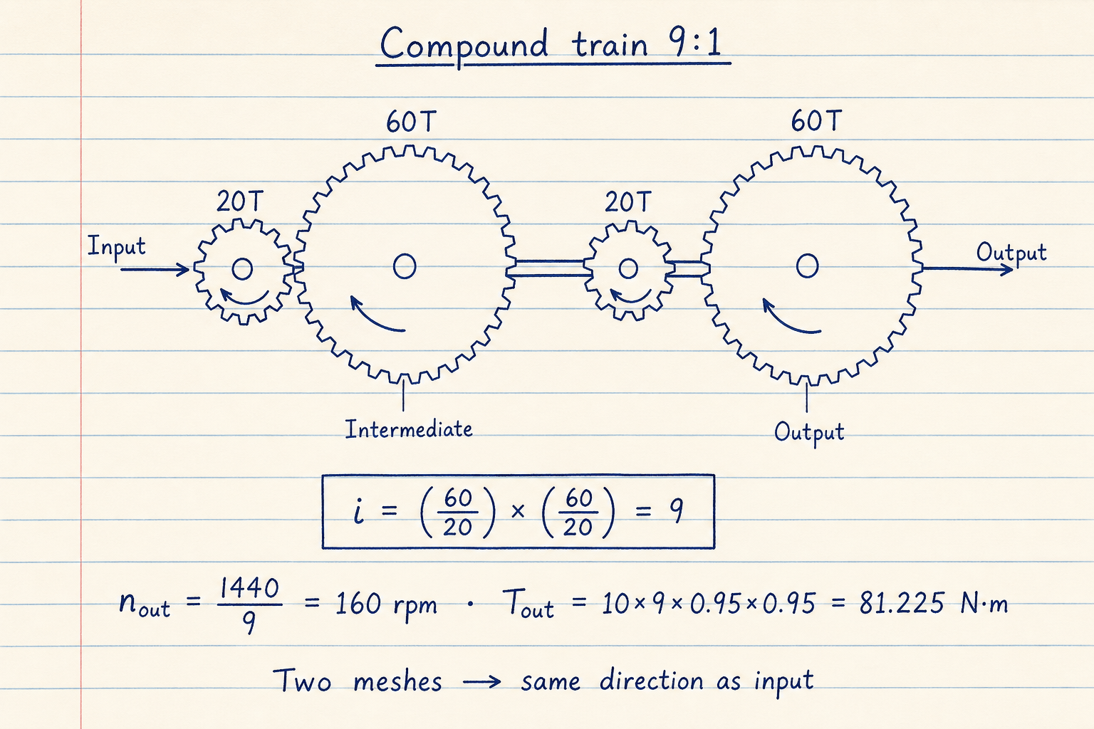
Default CALCULATE path: i = 3 × 3 = 9, n_out = 1440/9 = 160 rpm, T_out = 10 × 9 × 0.95 × 0.95 = 81.225 N·m.
Two external meshes without extra idlers leave the output turning the same way as the input.
Idlers flip direction. They do not change the ratio.
In a simple train, only the gears that change speed enter the ratio product. An idler between driver and driven cancels from the magnitude of i and adds one mesh, so rotation flips again.
Use Simple train + idlers when the sketch is a single mesh with spacers for center distance or direction. Set Extra idlers on any mode when you add those meshes outside the counted stages.
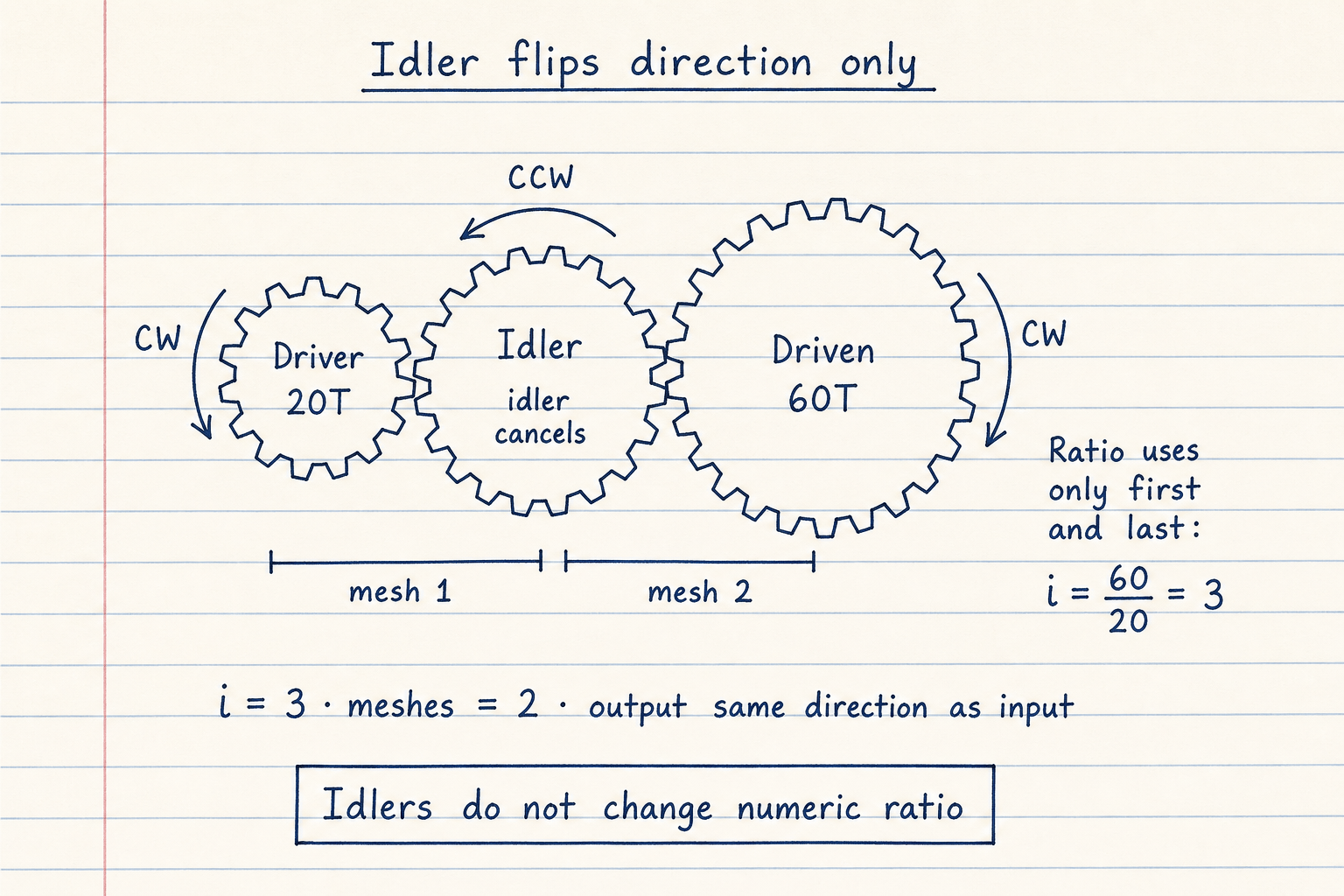
20T → idler → 60T keeps i = 3. Two meshes → output same direction as input.
Odd mesh count without that idler would reverse the output.
Target RPM reverse-solves ratio. Tooth search suggests pairs.
Clock and instrument designers often hunt integer tooth counts for a hard ratio. This pad's Target RPM mode first computes i_req = n_in / n_out, splits equal stages as i_req^(1/N), then searches nearby integer pairs (pinions 12–40, wheels 18–120) for a close product.
Treat suggestions as a starting sketch, not a finished gearbox. Confirm module, center distance, and strength on the spur or helical pads before you cut metal.
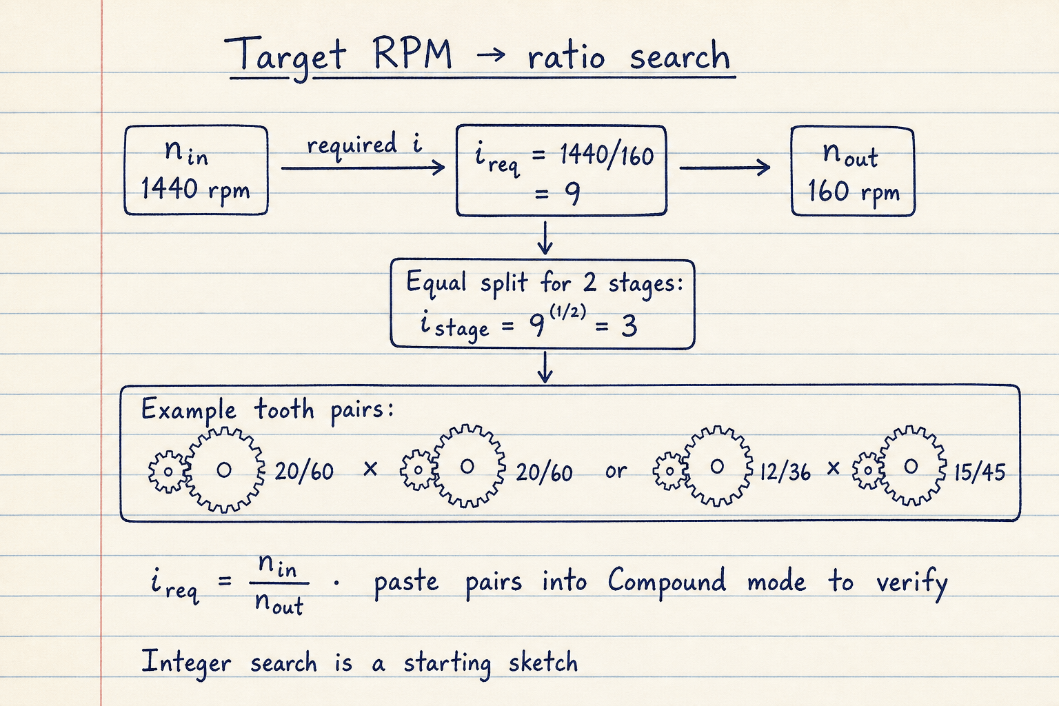
1440 rpm in and 160 rpm out → i_req = 9. Two equal stages → about 3:1 each.
Paste a suggested pair into Compound mode to verify cascade RPM and torque with your efficiencies.
Efficiency stacks. Stress sizing is a different pad.
Ideal torque scales with i. Real meshes lose a few percent to friction and churning. Enter each compound stage efficiency (defaults 95%). Path efficiency is the product. A 9:1 train at 95% × 95% turns 10 N·m into 81.225 N·m, not 90.
This pad does not size tooth bending, contact stress, worm starts, or planetary tables. After you lock i and speeds, continue with spur/helical geometry or a catalog gearbox. Pinions under about 17 teeth on standard full-depth spur profiles can undercut — the pad warns when a stage driver is under 17.
Pair pad vs train pad
Use the gear ratio calculator for a quick pair by teeth or pitch diameter, or a fixed two-stage compound with one path efficiency. Use this gear train calculator when you need three or four stages, per-stage η, cascade speeds, idler-aware simple trains, or a target-RPM reverse solve with tooth suggestions.
Neither pad is a vehicle MPH tool. For motor power after you know load torque and RPM, open the motor gearbox calculator.
Worked example
Default Compound train: 20/60 × 20/60, 1440 rpm, 10 N·m, 95% per stage. Reproduce on CALCULATE.
- Leave Input mode on Compound train with 2 stages. Confirm 20/60 and 20/60, efficiencies 95, 1440 rpm, 10 N·m, idlers 0.
- CALCULATE. Stage ratios 3 and 3. Overall i = 9.
- Cascade: 1440 → 480 rpm after stage 1 → 160 rpm out.
- η_total = 0.95 × 0.95 = 0.9025. T_out = 10 × 9 × 0.9025 = 81.225 N·m.
- Direction same as input (two meshes). Optional: Target RPM 1440 → 160 also returns i_req = 9.
Result: Default: ratio 9.0:1, 160 rpm out, 81.225 N·m, same direction.
When to use
- Sizing a two- to four-stage compound reducer before housing layout
- Checking cascade RPM on intermediate shafts
- Estimating output torque with per-stage efficiency
- Simple trains where idlers set direction or span
- Finding required ratio from target output RPM and nearby tooth pairs
Limitations
- Spur/external mesh model. No planetary, worm, or bevel kinematics.
- Maximum four compound stages in the UI.
- Does not size tooth bending, contact stress, backlash, or center distance.
- Tooth-pair search is a bounded integer screen, not a full clock DFS with shaft constraints.
- Not a vehicle MPH tool (no axle ratio or tire height).
- Not a substitute for a signed gearbox selection on safety-critical drives.
FAQ
- How is this different from the gear ratio calculator?
- Gear ratio covers pair-by-teeth, pair-by-diameter, and a fixed two-stage compound with one efficiency. This pad adds up to four stages, per-stage η, cascade RPM, simple+idler mode, and target-RPM reverse solve with tooth suggestions.
- How do you calculate a multi-stage gear train ratio?
- Multiply stage ratios. Each stage is driven teeth ÷ driver teeth. Overall i = i1 × i2 × … . Output speed is n_in / i.
- Do idler gears change gear ratio?
- No. In a simple train, idlers change direction and spacing only. Only compound gears fixed on the same shaft multiply the ratio.
- What does train value mean?
- Train value is 1/i, equal to ideal n_out/n_in. Some textbooks quote train value instead of reduction ratio.
- How does efficiency affect torque here?
- T_out = T_in × i × η_total. On the default 9:1 with 95% per stage, η_total = 90.25% and 10 N·m becomes 81.225 N·m.
- What does Target RPM mode do?
- It sets i_req = n_in / n_out, shows an equal-stage split, and searches nearby integer tooth pairs you can paste into Compound mode.
Gear Ratio Calculator
Gear ratio, output RPM, and torque for spur pairs, compound trains, direct ratio, speed solve, or idler trains.
Open calculatorSpur Gear Design Calculator
ISO 53 spur blank, pair a/εα, tooth proportions, Lewis bending, and Ft/Fr force triangle — six modes with 2D sketches.
Open calculatorMotor Gearbox Selector Calculator
Motor power from load torque, or gearbox output torque from motor power, ratio, SF, and efficiency.
Open calculator