You need helical blank diameters, lead, pair centre distance, contact ratios, or a first-pass Lewis check with axial thrust before you freeze a housing or order a hob. This pad covers six input modes — blank geometry, pair / centre distance, Strength (Lewis), lead & axial pitch, contact ratios, and force triangle — each with a distinct animated 2D Results sketch.
Defaults open on Blank geometry: mn = 2 mm, 20 teeth, β = 15°, αn = 20°, mating 40 teeth, face 25 mm. CALCULATE returns pitch diameter ≈ 41.41 mm, tip ≈ 45.41 mm, root ≈ 36.41 mm, lead ≈ 485.5 mm. Switch to Pair for a ≈ 62.12 mm and εγ ≈ 2.59, or Strength for Lewis FoS with Ft/Fa/Fr. Math stays in your browser.
It sits under Mechanical Calculators next to the spur gear calculator, gear ratio calculator, and gear train calculator.
Formula
- Normal system: mt = mn/cosβ, d = mt·Z = mn·Z/cosβ, da = d+2mn, df = d−2.5mn.
- Transverse pressure angle: tan αt = tan αn / cosβ. Base diameter db = d·cos αt.
- Lead L = π·mn·Z/sinβ. Axial pitch px = π·mn/sinβ. Virtual teeth zv = Z/cos³β.
- Pair (zero shift): a = mn(Z1+Z2)/(2 cosβ). εγ = εα + εβ with εβ = b·sinβ/(π·mn).
- Forces: Fa = Ft·tanβ, Fr = Ft·tanαn/cosβ. Lewis: σ = Ft/(Cv·b·mn·Y), Cv = 6/(6+v), Y from zv.
Reproduce the default Blank / Pair path on CALCULATE:
| Quantity | Value |
|---|---|
| mn / Z / β / αn | 2 mm · 20T · 15° · 20° |
| Mating teeth / face | 40 · 25 mm |
| mt / pitch d | ≈ 2.071 / 41.41 mm |
| Tip / root | ≈ 45.41 / 36.41 mm |
| Centre distance (Pair mode) | ≈ 62.12 mm |
| Lead / εγ | ≈ 485.5 mm · ≈ 2.59 |
How it works
Pick Blank, Pair, Strength (Lewis), Lead, Contact ratios, or Force triangle. ISO 21771-style normal system (mn, αn, β, Z), centre distance, εγ, lead/px, undercut warn on zv, Lewis with helical Cv, and Ft/Fa/Fr. Each mode draws a distinct animated 2D Results sketch.
Pick Input mode: Blank geometry (default), Pair / centre distance, Strength (Lewis), Lead & axial pitch, Contact ratios, or Force triangle. The animated 2D sketch in Results switches with the mode (Play/Pause). Enter teeth, normal module, helix (0–45°; β = 0 is the spur limit), and mode-specific fields. Mating teeth required for Pair and Contact. Face width feeds εβ and Lewis. CALCULATE fills Results. Editing clears Results. RESET restores mn2 · 20T · β15 · mate 40.
Normal module and helix angle set the pitch diameter
Shop references start from tooth size in the normal plane. The hob sees mn; the shaft sees d = mn·Z/cosβ because the transverse module grows with helix angle.
Defaults use mn = 2 mm, Z = 20, β = 15° so mt ≈ 2.071 mm and d ≈ 41.41 mm — larger than the spur twin at the same mn and Z. Set β = 0 to recover spur diameters on this pad.
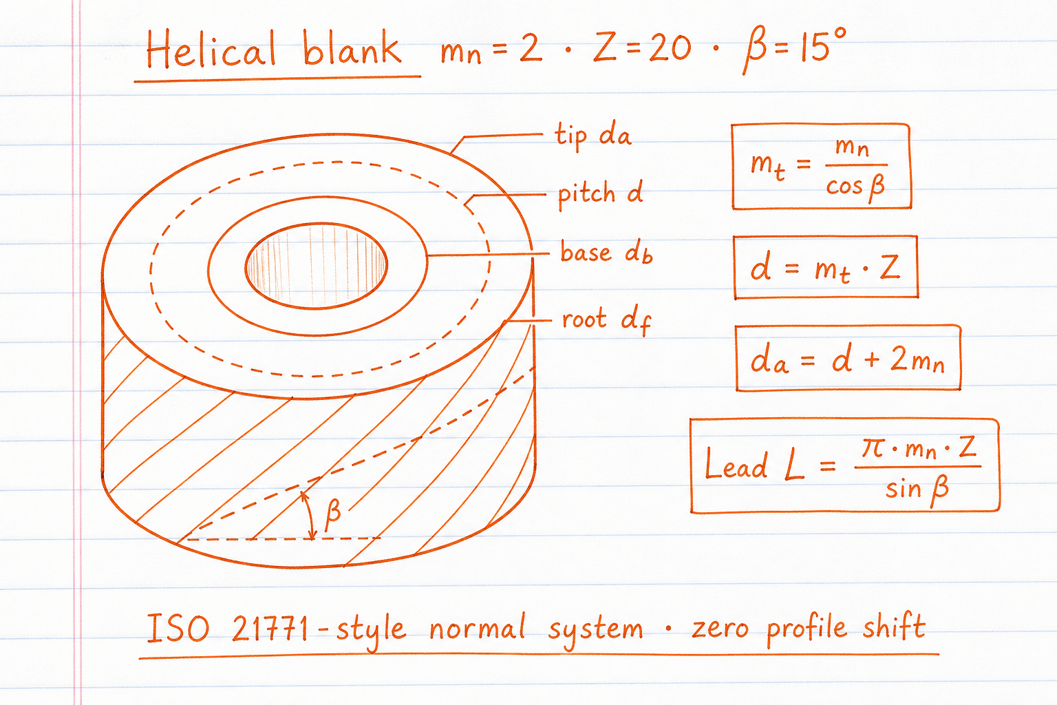
Addendum and dedendum stay on mn (ha = mn, hf = 1.25mn) in the normal system with zero profile shift.
Lead L = π·mn·Z/sinβ is the axial advance for one full turn — useful for milling setup.
Centre distance grows with cosβ — and hands must oppose
Standard external spacing is a = mn(Z1+Z2)/(2 cosβ). Parallel shafts need the same mn and β but opposite helix hands.
Default mate 40T on mn2 β15 gives a ≈ 62.12 mm and i = 2 — about 3.5% longer than the spur a = 60 mm at the same teeth and module. Total contact ratio εγ = εα + εβ uses face width for the axial part.
Default helical pair vs spur twin:
| Case | Inputs | Key result |
|---|---|---|
| Helical default | 20T+40T · mn2 · β15° | a ≈ 62.12 mm · εγ ≈ 2.59 |
| β = 0 (spur limit) | Same teeth · mn2 | a = 60 mm |
| Single blank | Mating teeth = 0 | Diameters + lead only |
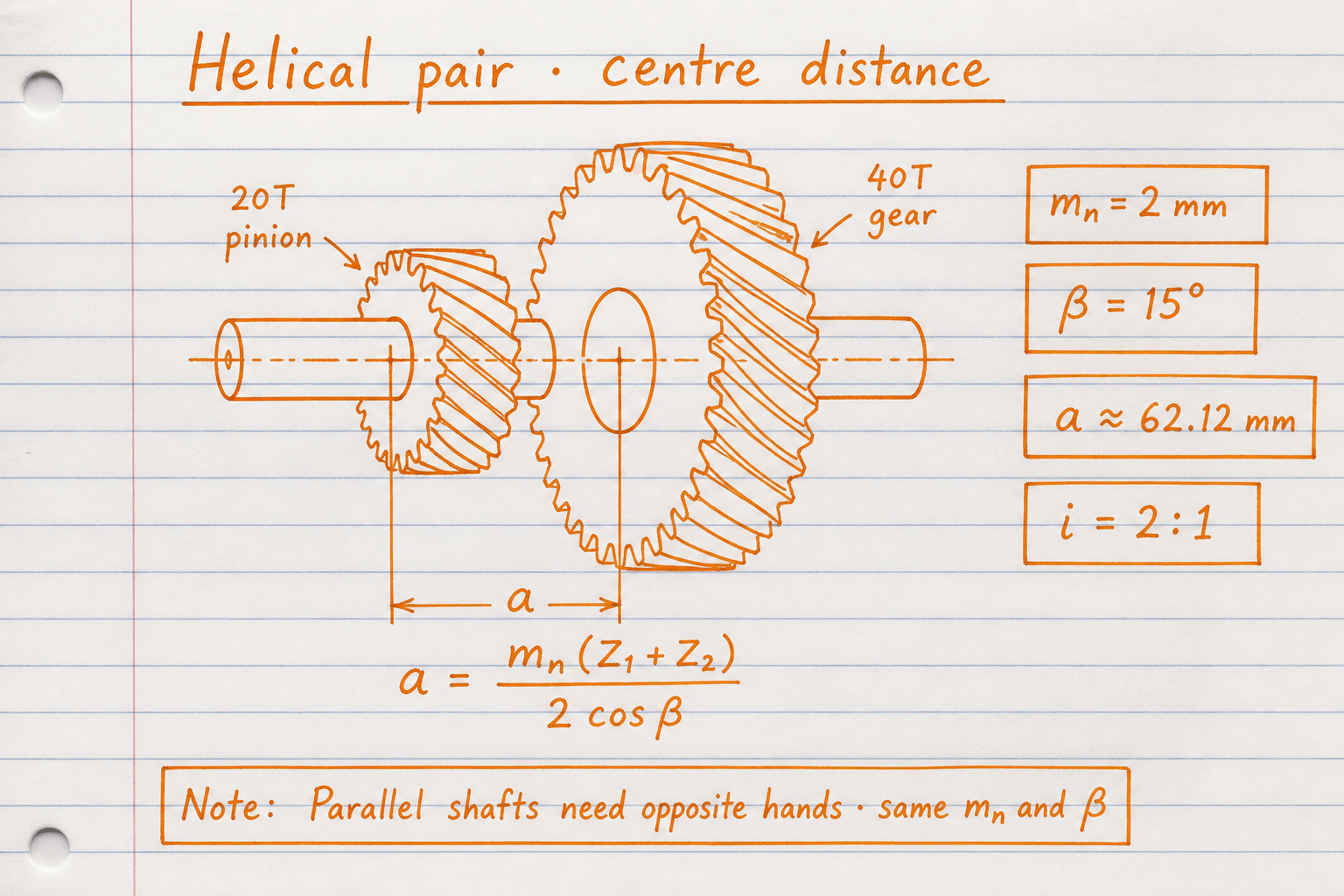
Pitch cylinders set shaft spacing; tip diameters do not.
Keep αn, mn, and |β| identical on both members for a standard parallel mesh.
Virtual teeth decide undercut risk
Helical gears behave like a virtual spur with zv = Z/cos³β. Undercut screening uses that count against Z_min ≈ 2/sin²αn. A low real tooth count can still clear the warn if β is large enough to lift zv.
Profile shift and ISO span / ball measurement live on deeper rating pads. This pad warns only — it does not size xn or export tooth form.
Lewis helical screen includes axial thrust
Cutting and force calculators separate geometry from load. Strength mode uses σ = Ft/(Cv·b·mn·Y) with Cv = 6/(6+v), Y from round(zv), plus Fa = Ft·tanβ and Fr = Ft·tanαn/cosβ.
Example path: mn3, 30T, β15°, b = 35 mm, 5 kW at 1200 rpm, allowable 140 MPa → Ft ≈ 854 N, Fa ≈ 229 N, σ ≈ 49.3 MPa, FoS ≈ 2.84 (Pass at ≥ 1.5). Full ISO 6336 / AGMA rating is out of scope.
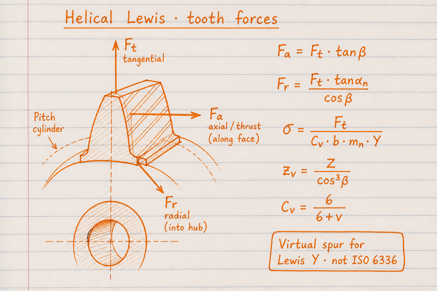
Axial thrust Fa loads bearings along the shaft — size them for Fa, not only Ft.
Use FoS as a preliminary go/no-go before a catalog rating or ISO 6336 worksheet.
What this pad does not generate
CAD tooth-profile scripts, span/ball dimensions, and crossed-axis helical layouts are out of scope. Use this pad for normal-system blank sizing, pair a/εγ, lead, undercut warn on zv, and Lewis screening with thrust — then hand off to CAD or a signed rating.
Worked example
Default Blank geometry: mn = 2 mm, Z = 20, β = 15°, αn = 20°, mating Z = 40, b = 25 mm. Reproduce on CALCULATE.
- Leave Input mode on Blank geometry, 20° normal pressure angle.
- Confirm teeth 20, normal module 2, helix 15°, mating 40, face 25.
- CALCULATE. d ≈ 41.41 mm, da ≈ 45.41 mm, df ≈ 36.41 mm, L ≈ 485.5 mm. Results shows the 2D blank sketch.
- Switch to Pair / centre distance → a ≈ 62.12 mm, i = 2. Contact ratios → εγ ≈ 2.59.
- Optional: Strength mn3 · 30T · β15 · b35 · 5 kW · 1200 rpm · 140 MPa → FoS ≈ 2.84 Pass.
Result: Default blank: d ≈ 41.41 mm. Pair: a ≈ 62.12 mm, i 2:1. Strength example: FoS ≈ 2.84 on the mn3/30T path.
When to use
- Sizing a helical blank OD before turning or hobbing
- Setting parallel-shaft centre distance for a helical pair
- Computing lead and axial pitch for milling setup
- Screening εα / εβ / εγ before housing tryout
- Checking undercut risk via virtual teeth
- First-pass Lewis FoS or Ft/Fa/Fr before catalog selection
Limitations
- External parallel-shaft helical only. No crossed-axis, herringbone, bevel, worm, or internal gears.
- Zero profile shift; no tip relief or backlash design.
- No span, measurement-over-balls, or tooth-form export.
- Lewis + helical Barth Cv is a preliminary bending screen, not ISO 6336 / AGMA rating.
- Lewis Y uses the common 20° table on virtual teeth for all αn.
- At β = 0 the pad reports spur diameters and centre distance; lead and axial pitch are undefined.
- Hand (RH/LH) on the sketch is a mesh rule reminder — not a signed CAD twist export.
- Not a substitute for a signed gearbox selection on safety-critical drives.
FAQ
- How do I calculate helical gear pitch diameter?
- d = mn·Z/cosβ (or mt·Z with mt = mn/cosβ). Defaults: 2×20/cos15° ≈ 41.41 mm.
- What is the helical centre distance formula?
- For two external gears with no profile shift, a = mn(Z1+Z2)/(2 cosβ). Use Pair / centre distance mode with mating teeth set.
- What do the six input modes change?
- Each mode picks which fields matter and which 2D Results sketch you see: blank diameters, pair a/εγ, Lewis FoS, lead/px unwrap, contact-ratio stack, or Ft/Fa/Fr triangle. Geometry formulas stay the same underneath.
- Why is helical centre distance larger than spur?
- Because pitch diameters inflate with 1/cosβ. Same mn and teeth at β = 15° sit farther apart than at β = 0°.
- What is virtual number of teeth?
- zv = Z/cos³β. Lewis Y and undercut screening use this equivalent spur count.
- Do parallel helical gears use the same hand?
- No. Same mn and β, opposite hands (RH with LH). Same-hand pairs are for crossed shafts — not this pad.
- Is this ISO 6336 strength?
- No. Strength mode is Lewis with helical Cv and Ft/Fa/Fr. ISO 6336 / AGMA 2001 dynamic and pitting factors are not computed.
Spur Gear Design Calculator
ISO 53 spur blank, pair a/εα, tooth proportions, Lewis bending, and Ft/Fr force triangle — six modes with 2D sketches.
Open calculatorGear Ratio Calculator
Gear ratio, output RPM, and torque for spur pairs, compound trains, direct ratio, speed solve, or idler trains.
Open calculatorGear Train Calculator
Multi-stage compound gear train (1–4 stages), simple+idler path, or target-RPM reverse ratio with tooth-pair search.
Open calculator