Tolerance zones · H7/g6 · live
- Fit designation
- H7/g6
- Fit type
- Clearance
- Hole limits
- 50.0000 – 50.0273 mm
- Shaft limits
- 49.9737 – 49.9908 mm
- Min clearance
- 0.0092 mm
- Max clearance
- 0.0536 mm
- Mean clearance
- 0.0314 mm
- Tolerance band
- 0.0444 mm
EI 0.0 / ES 27.3 µm
ei -26.3 / es -9.2 µm
Hole min − shaft max
Hole max − shaft min
IT hole 27.3 + shaft 17.1 µm
Preview updates as you type. Press CALCULATE to lock Results.
You need hole and shaft limit dimensions from an ISO 286 callout like H7/g6 — and whether that pair is clearance, transition, or interference. This pad takes nominal size plus hole and shaft classes (or a common fit preset), returns limit sizes, ES/EI/es/ei deviations in micrometres, min/max clearance, and fit type. Switch Hole basis (H) or Shaft basis (h) the way standard limits-and-fits tools do.
Defaults open on Hole basis · H7/g6 · 50 mm. CALCULATE returns hole ≈ 50.000–50.027 mm, shaft ≈ 49.974–49.991 mm, min clearance ≈ 0.009 mm, max ≈ 0.054 mm — Clearance. Try H7/p6 for press or G7/h6 for shaft-basis sliding. Math stays in your browser.
It sits under GD&T & Metrology Calculators next to the GD&T fit calculator and surface roughness converter. This pad is an ISO class limits estimator — not a full licensed ISO 286 table reprint.
Formula
- Tolerance unit i = 0.45 × ³√D + 0.001D (µm).
- IT grade ≈ multiplier × i (IT6=10, IT7=16, IT8=25, IT9=40, IT11=100).
- Hole H: EI = 0, ES = +IT. Other hole letters mirror the matching shaft letter (screening).
- Shaft: es from letter (g ≈ −2.5∛D, h = 0, …), ei = es − IT.
- Limits: hole = nom + EI/ES; shaft = nom + ei/es (convert µm → mm).
- Min clearance = hole min − shaft max · Max clearance = hole max − shaft min.
- Clearance if min ≥ 0 · Interference if max ≤ 0 · else Transition.
Reproduce the default Hole-basis H7/g6 · 50 mm path on CALCULATE:
| Quantity | Value |
|---|---|
| Inputs | 50 mm · H7 / g6 · Hole basis |
| Hole limits | ≈ 50.000 – 50.027 mm (EI 0 / ES ≈ +27 µm) |
| Shaft limits | ≈ 49.974 – 49.991 mm |
| Min / max clearance | ≈ 0.009 / 0.054 mm → Clearance |
| Example | H7/p6 at 50 mm → Interference stack |
How it works
Pick hole-basis or shaft-basis, a common fit preset (H7/g6, H7/p6, G7/h6…), or any hole/shaft class. Returns limit dimensions, ES/EI/es/ei deviations, and clearance or interference range. Screening formulas — verify critical fits against ISO 286 tables.
Pick Hole basis (H) or Shaft basis (h) — switching basis shows that system’s presets and loads the first one (H7/g6 or G7/h6). Tap another fit preset or choose hole/shaft classes from the lists. Enter nominal size (0.1–500 mm). CALCULATE locks Results and the live tolerance-zone sketch (Play/Pause). Editing clears Results. RESET restores 50 mm H7/g6.
Letter and number — what H7/g6 means
Limits-and-fits calculators decode the same alphanumeric system: the letter is the fundamental deviation (where the tolerance zone sits relative to nominal), and the number is the IT grade (how wide the zone is).
Uppercase letters describe holes; lowercase describe shafts. H holes start at nominal (EI = 0). g shafts sit slightly under nominal so H7/g6 always clears. This pad uses ISO-style screening formulas for IT and letter deviations — close enough for design checks, not a substitute for licensed tables on critical production.
Callout anatomy:
| Part | Example | Letter | Number |
|---|---|---|---|
| Hole | H7 | H = EI at nominal | 7 = IT7 width |
| Shaft | g6 | g = slight under size | 6 = IT6 width |
| Fit | H7/g6 | Hole basis sliding | Always clearance |
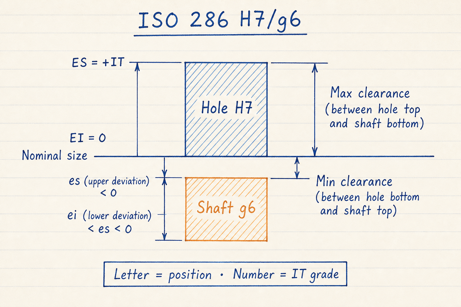
Default CALCULATE path at 50 mm: hole above nominal, shaft below → clearance.
Zone widths grow with IT grade and with larger nominal diameters.
Hole basis vs shaft basis
Hole basis (H) keeps the hole lower limit at nominal and varies the shaft; shaft basis (h) keeps the shaft upper limit at nominal and varies the hole (for example G7/h6).
Most machining shops prefer hole basis because standard reamers and gauges are built around H holes. Use shaft basis when the shaft is already standardized (drill rod, purchased pin) and the hole must be opened to suit.
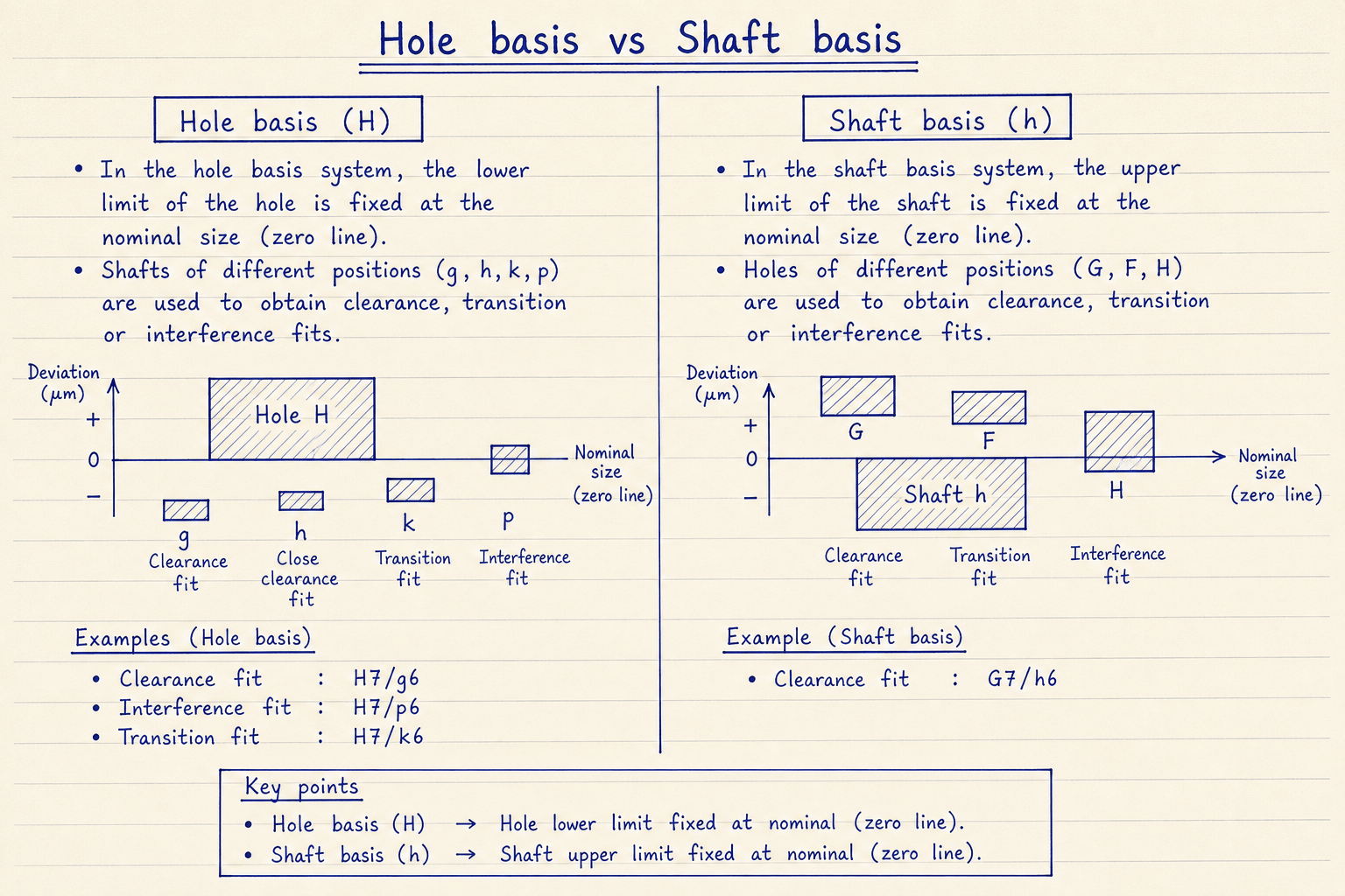
Hole basis presets: H7/g6, H7/h6, H7/k6, H7/p6, H7/s6.
Shaft basis example: G7/h6 sliding, F8/h7 close running.
Clearance, transition, interference
Limits-and-fits tools classify the same three outcomes every pad reports. Clearance: largest shaft still smaller than smallest hole. Interference: smallest shaft still larger than largest hole. Transition: either outcome is possible depending on where each part lands in its zone.
Min clearance = hole min − shaft max. Max clearance = hole max − shaft min. Negative clearance is interference. Presets on this pad cover sliding (H7/g6), locational (H7/h6), transition (H7/k6, H7/n6), and press (H7/p6, H7/s6).
Common hole-basis presets at a glance:
| Preset | Typical use | Fit class |
|---|---|---|
| H7/g6 | Sliding / precise location | Clearance |
| H7/h6 | Locational clearance | Clearance |
| H8/f7 | Close running with lube | Clearance |
| H7/k6 | Keying / light transition | Transition |
| H7/p6 | Press / interference | Interference |
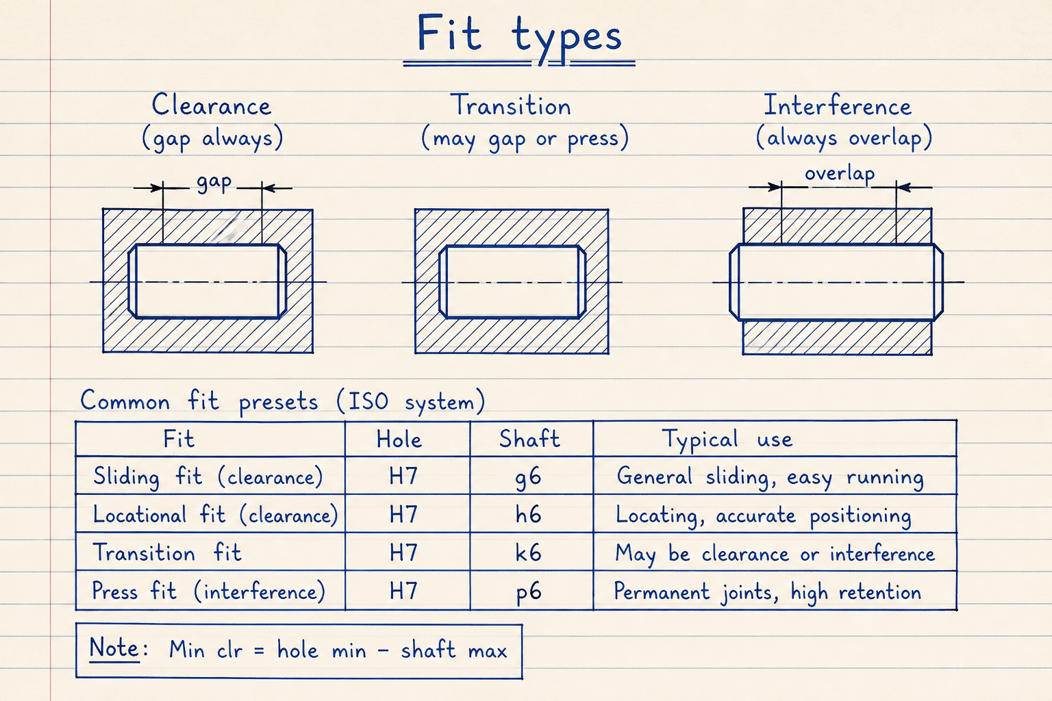
Default 50 mm H7/g6 → Clearance ≈ 0.009–0.054 mm.
Switch to H7/p6 when you need a press stack for the same nominal.
Worked example
Default Hole basis · H7/g6 · 50 mm. Reproduce on CALCULATE.
- Leave Hole basis and H7/g6 preset. CALCULATE → hole ≈ 50.000–50.027 mm.
- g6 shaft ≈ 49.974–49.991 mm · min clearance ≈ 0.009 mm · max ≈ 0.054 mm → Clearance.
- Preset H7/p6 at 50 mm → interference stack (min clearance negative).
- Shaft-basis example: G7/h6 — hole opens above nominal while shaft max sits at nominal.
Result: Default: Clearance fit H7/g6 at 50 mm (~9–54 µm). Presets cover sliding through heavy press.
When to use
- Looking up ISO hole/shaft limit dimensions from a class callout
- Comparing clearance vs transition vs interference for a nominal size
- Choosing among common presets (H7/g6, H7/p6, G7/h6…)
- Reading ES/EI/es/ei deviations in micrometres for drawings
- Teaching hole-basis vs shaft-basis systems
Limitations
- Uses screening formulas for IT grades and fundamental deviations — not a full ISO 286-1/286-2 table reprint.
- Limited class set (common H/G/F/JS holes and d–s shafts); exotic letters need licensed tables.
- r/s/t/u and some hole K–U delta adjustments are approximated or omitted.
- Nominal clamped to 0.1–500 mm; verify edge sizes against the standard size bands.
- Not a GD&T MMC/LMC virtual-condition tool (use the GD&T fit calculator).
FAQ
- What is H7/g6?
- A common hole-basis sliding fit: H7 hole (lower limit at nominal, IT7 wide) with a g6 shaft (slightly under nominal, IT6 wide). At 50 mm this pad returns roughly 9–54 µm clearance.
- Hole basis vs shaft basis?
- Hole basis (H) fixes the hole lower limit at nominal and varies the shaft. Shaft basis (h) fixes the shaft upper limit at nominal and varies the hole (for example G7/h6). Most shops use hole basis.
- How accurate are these numbers?
- IT and letter deviations use ISO-style screening formulas. They match published bands closely for common sizes, but critical production fits should be checked against licensed ISO 286 tables.
- Clearance vs transition vs interference?
- Clearance: min clearance ≥ 0 (always a gap). Interference: max clearance ≤ 0 (always overlap). Transition: the range crosses zero — either outcome is possible.
- What are ES, EI, es, ei?
- Hole upper/lower deviations (ES/EI) and shaft upper/lower deviations (es/ei) in micrometres. Add them to the nominal size to get limit dimensions.
GD&T Fit Calculator
Shaft-hole MMC/LMC clearance, fit type, and optional virtual-condition go-gauge envelopes.
Open calculatorGD&T True Position Calculator
Diametral true position from X/Y deviations with RFS, MMC, or LMC bonus — Metric or Imperial, 2D or 3D.
Open calculatorSurface Roughness Converter
Convert Ra, Rz, Rq/RMS, Rt, CLA, and ISO N-grades with process-based Rz/Ra screening factors.
Open calculator