You have a plane-stress state at a point (σx, σy, τxy) and need the principals, max shear, and how the element transforms when you rotate it. This pad builds Mohr's circle for that 2D state, reports σ1 and σ2, in-plane and absolute max shear (with σ3 = 0), principal and max-shear angles, transformed stresses at your θ, and a plane-stress von Mises screen.
Defaults open on Metric: σx = 80 MPa, σy = −40 MPa, τxy = 30 MPa, θ = 0°. CALCULATE returns σ1 ≈ 87.08 MPa, σ2 ≈ −47.08 MPa, τ_max ≈ 67.08 MPa, θp ≈ 13.28°, and von Mises ≈ 117.9 MPa. Switch to Imperial (ksi) when your FEA or handbook values are already in ksi. Math stays in your browser.
It sits under Mechanical Calculators. For a full equivalent-stress pad from any stress components, use the von Mises calculator. Pair principals with a yield check on the safety factor calculator.
Formula
- Center C = (σx + σy) / 2. Radius R = √(((σx − σy)/2)² + τxy²).
- Principals: σ1 = C + R, σ2 = C − R. In-plane max shear τ_max = R.
- Principal angle: 2θp = atan2(2τxy, σx − σy), θp = 2θp / 2 (to the σ1 plane, CCW from x).
- Max-shear plane: θs = θp − 45°. Physical rotation θ → 2θ on the circle.
- Transform: σx′ = C + ((σx−σy)/2)cos2θ + τxy sin2θ; τx′y′ = −((σx−σy)/2)sin2θ + τxy cos2θ.
- Plane stress: σ3 = 0. Absolute max shear = ½(σ_max − σ_min) over {σ1, σ2, 0}. von Mises = √(σ1² − σ1σ2 + σ2²).
Reproduce the default Metric path on CALCULATE:
| Check | Value on this pad |
|---|---|
| Inputs | σx 80, σy −40, τxy 30 MPa, θ 0° |
| C / R | 20 MPa · ≈ 67.08 MPa |
| σ1 / σ2 | ≈ 87.08 / −47.08 MPa |
| θp / 2θp | ≈ 13.28° · ≈ 26.57° |
| τ_max = τ_abs | ≈ 67.08 MPa (opposite-sign principals) |
| von Mises | ≈ 117.9 MPa |
How it works
Pick Metric or Imperial, enter σx, σy, τxy, and optional θ. The diagram previews the circle and 2θ diameter while you edit. CALCULATE locks principals, in-plane and absolute max shear, angles, transformed stresses, and plane-stress von Mises. Plane stress sets σ3 = 0.
Pick Metric (MPa) or Imperial (ksi). Enter σx, σy, and τxy. Optional Transform angle θ is the physical-plane rotation from the x-axis (CCW positive); leave 0 to keep the unrotated element. The live diagram previews the circle, stress element, and 2θ diameter while you edit. CALCULATE locks the Result cards (principals, shears, angles, von Mises). Editing any input clears the lock. RESET restores defaults for the active unit system.
Building the circle from σx, σy, and τxy
Mohr's circle is the graphical form of the plane-stress transformation equations. The center sits at the average normal stress. The radius is the distance from that center to the point representing the x-face.
On this pad, CALCULATE the defaults. You should see C = 20 MPa and R ≈ 67.08 MPa. Principals land at the σ-axis ends of the horizontal diameter. That is the same algebra as σ1,2 = C ± R without drawing anything by hand.
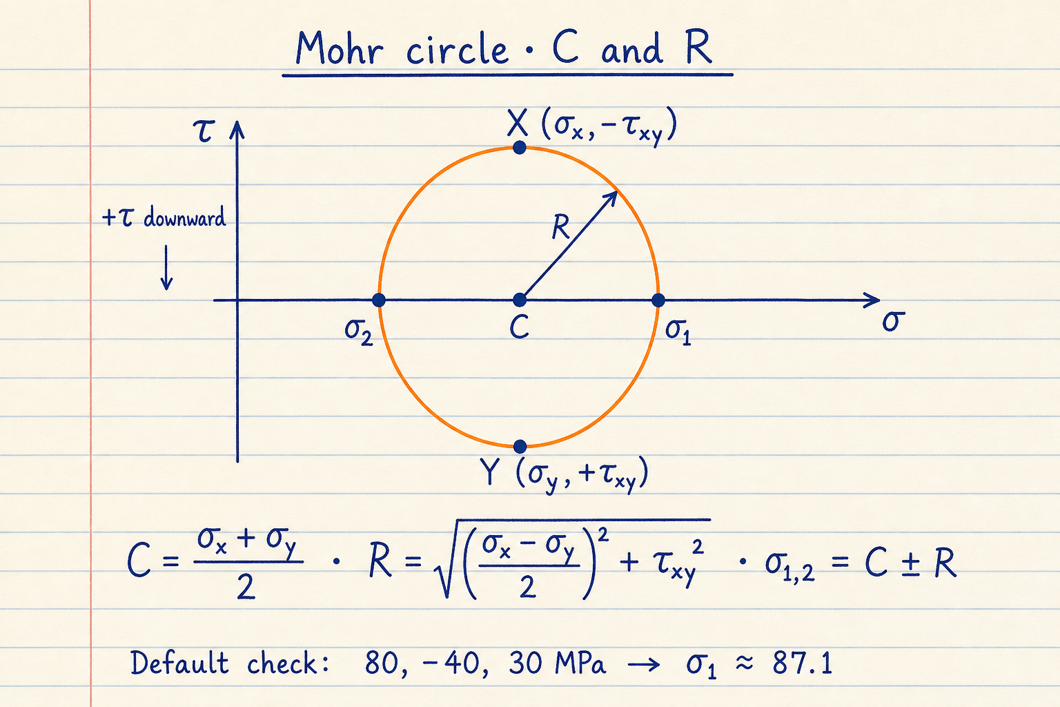
X plots at (σx, −τxy) and Y at (σy, +τxy) so a counter-clockwise physical rotation sweeps counter-clockwise as 2θ on the circle when +τ is drawn downward.
σ1 and σ2 sit where the circle crosses the σ-axis. Shear is zero on those planes by definition.
Why the angle doubles on the circle
Stress transformation uses sin 2θ and cos 2θ. Rotate the element by θ and the representative point walks 2θ around Mohr's circle. A 90° physical turn (x-face becomes the old y-face) is a 180° walk on the circle, which is why X and Y sit at opposite ends of a diameter.
Enter Transform angle θ = 30° on the check case σx = 100, σy = 40, τxy = 30 MPa. CALCULATE should give σx′ ≈ 110.98 MPa and τx′y′ ≈ −10.98 MPa, with 2θ = 60° on the diagram diameter.
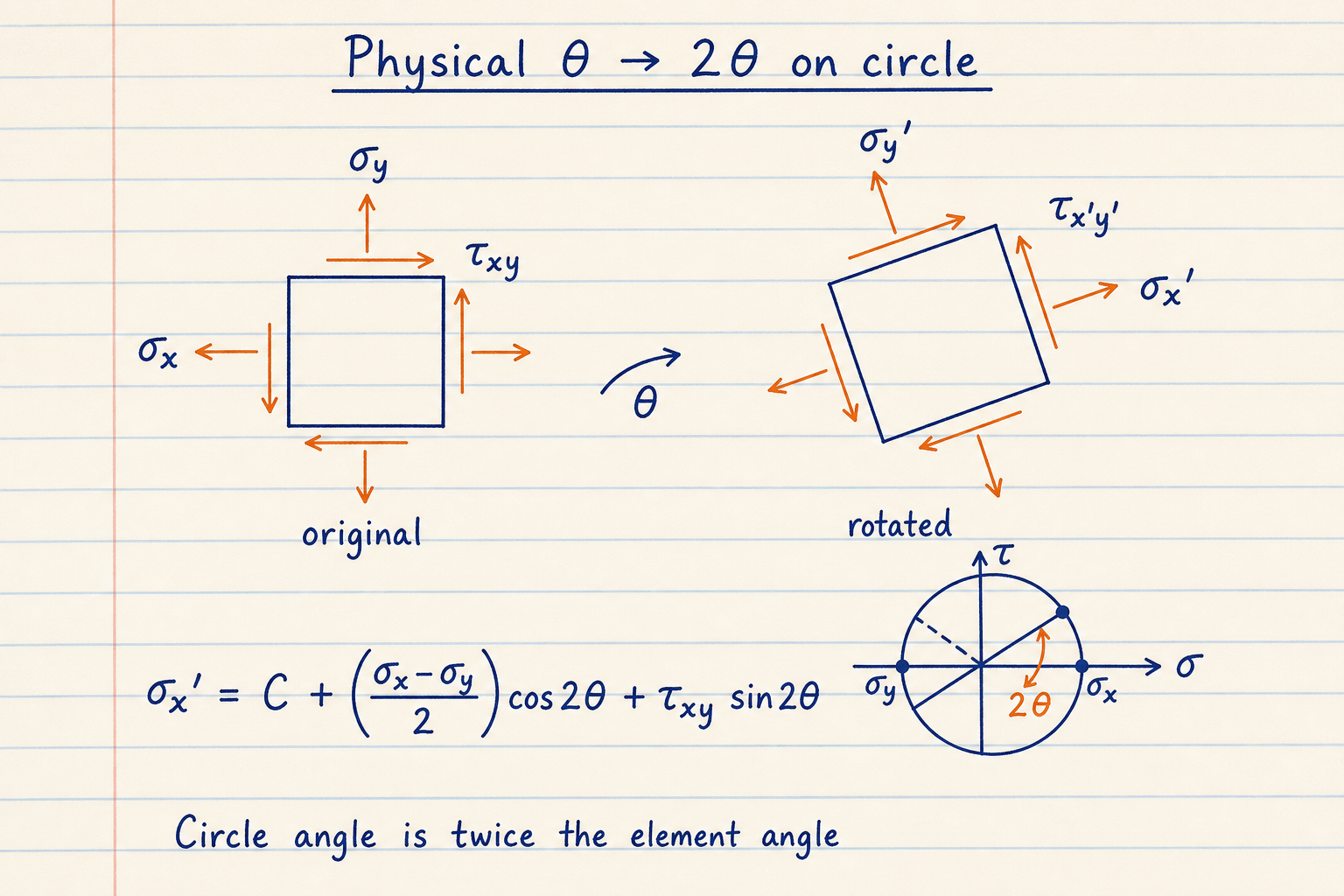
θ is measured counter-clockwise from the reference x-axis on the physical element.
This pad reports σx′, σy′, and τx′y′ at your θ after CALCULATE, plus the live diameter on the circle.
In-plane shear vs absolute max shear with σ3 = 0
In-plane max shear is always the circle radius R. For plane stress the third principal is zero. Absolute max shear is half the spread between the algebraically largest and smallest of {σ1, σ2, 0}.
When σ1 and σ2 have opposite signs, that spread is σ1 − σ2, so τ_abs = R. When both principals are tension (or both compression), the larger circle runs from σ3 = 0 to the farther principal, and τ_abs exceeds R. The default opposite-sign case keeps them equal at ≈ 67.08 MPa. The 100 / 40 / 30 MPa case shows τ_max ≈ 42.43 MPa but τ_abs ≈ 56.21 MPa.
Same pad, two shear readouts:
| Case | τ_max (in-plane) | τ_abs (σ3 = 0) |
|---|---|---|
| 80 / −40 / 30 MPa | ≈ 67.08 MPa | ≈ 67.08 MPa |
| 100 / 40 / 30 MPa | ≈ 42.43 MPa | ≈ 56.21 MPa |
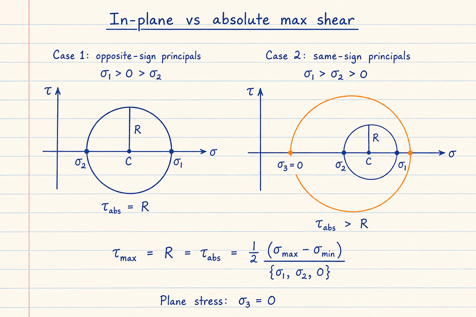
Opposite-sign principals: the in-plane circle already spans the extreme normals, so τ_abs = R.
Same-sign principals: include σ3 = 0 and the absolute shear grows. This pad reports both numbers so you do not miss that case.
Sign convention this pad uses
Tension is positive and compression is negative. Positive τxy tends to rotate the element counter-clockwise: on the +x face the shear points in +y. That matches standard mechanics-of-materials plotting with X at (σx, −τxy).
FEA postprocessors and some continuum texts plot shear the other way. Magnitudes of σ1, σ2, and R stay the same if you flip the shear sign consistently. Angles reverse. If your book plots +τ upward, the picture mirrors but the numbers for principals still match.
- θp is CCW from the x-axis to the σ1 plane
- θs = θp − 45° is one max in-plane shear plane
- Uniform state (σx = σy, τxy = 0) collapses R to 0; every direction is principal
von Mises from the principals, not a full design check
For plane stress this pad reports σv = √(σ1² − σ1σ2 + σ2²). That is the same distortion-energy value you get with σ3 = 0. Compare it to Sy only as a material-point screen. It is not a code check, fatigue life, buckling, or fracture assessment.
Need equivalent stress from a general 3D tensor? Use the related von Mises tool linked in the overview. For a simple Sy over stress comparison after you trust the stress state, use the related safety-factor tool.
What 3D Mohr tools add, and what we skip
Full 3D Mohr envelopes (six stress components, three nested circles) need σz, τxz, and τyz. University applets and 3D Mohr pages cover that eigenvalue problem. Principal stress directions in 3D are eigenvectors of the stress tensor, not a single in-plane θp.
This pad stays on plane stress: σx, σy, τxy, an optional transform angle θ, one circle, and the σ3 = 0 absolute-shear note. Plane strain and full 3D envelopes stay out of scope here on purpose.
- No plane-strain mode on this pad
- No 3D Mohr envelope or eigenvector plot
- No strain-rosette reduction (enter stresses you already have)
Worked example
Metric defaults: σx = 80 MPa, σy = −40 MPa, τxy = 30 MPa, θ = 0°.
- C = (80 + (−40)) / 2 = 20 MPa
- R = √(60² + 30²) = √4500 ≈ 67.08 MPa
- σ1 = 20 + 67.08 = 87.08 MPa, σ2 = 20 − 67.08 = −47.08 MPa
- 2θp = atan2(60, 120) ≈ 26.57°, so θp ≈ 13.28° to σ1
- τ_max = τ_abs ≈ 67.08 MPa; von Mises ≈ 117.9 MPa
Result: σ1 ≈ 87.08 MPa, σ2 ≈ −47.08 MPa, θp ≈ 13.28°, τ_max ≈ 67.08 MPa.
When to use
- Converting a 2D stress state into principal stresses and max shear
- Checking stress transformation at a known plane angle θ
- Screening ductile yield with plane-stress von Mises from σ1 and σ2
- Teaching or verifying hand Mohr constructions against a live circle
Limitations
- Plane stress only: σz = τxz = τyz = 0; not a 3D Mohr envelope
- Sign convention is mechanics-of-materials (CCW-positive shear); FEA sign flips change angles
- von Mises here is a material-point screen, not a design-code or fatigue check
- Does not reduce strain-gauge rosette readings to stresses for you
FAQ
- Do I need to click CALCULATE?
- Yes. Result cards stay as dashes until CALCULATE. The diagram can preview the circle, element rotation, and 2θ diameter from the typed stresses, but principals, angles, and von Mises lock in only after you submit. Editing an input clears the locked results.
- What is θp versus 2θp?
- 2θp is the central angle on Mohr's circle from the X-face point to the σ1 point. θp is half of that: the physical rotation from the x-axis to the major principal plane. This pad reports both, plus θs = θp − 45° for a max in-plane shear plane.
- Why are in-plane and absolute max shear different?
- In-plane max shear is always R. Absolute max shear also looks at σ3 = 0. If σ1 and σ2 have the same sign, the larger circle to zero makes τ_abs bigger than R. Opposite-sign cases keep them equal.
- Which shear sign convention should I use?
- Enter positive τxy when shear on the +x face points in +y (element tends to rotate CCW). That matches standard mechanics plotting with X at (σx, −τxy). If your FEA exports the opposite shear sign, flip τxy before comparing angles.
- Is the von Mises value a pass/fail for my part?
- No. It is √(σ1² − σ1σ2 + σ2²) for plane stress, useful next to Sy as a first screen. Real acceptance needs the right failure theory, factors, and whatever else your application requires. Use the dedicated von Mises tool when you have a fuller stress tensor.
Von Mises Stress Calculator
Distortion-energy equivalent stress from plane stress, principals, or a 3D tensor, with yield check.
Open calculatorSafety Factor Calculator
Factor of safety from strength ÷ stress. Yield or ultimate basis, material presets, and reverse solve modes.
Open calculatorBeam Stress and Deflection Calculator
Six textbook beam cases: max moment, shear, stress, deflection, slope, and L/360 check with animated 2D sketches.
Open calculator