Interference joint
Lamé contact pressure, hub hoop stress, friction torque and press force
- Contact pressure
- —
- Torque capacity
- —
- Assembly / axial force
- —
- Hub hoop stress
- —
- Hub von Mises
- —
- Shaft hoop stress
- —
- Hub safety factor
- —
- Shaft safety factor
- —
- Hub expansion
- —
- Shaft compression
- —
- Heat hub ΔT
- —
- Cool shaft ΔT
- —
You need a first-pass check on an interference joint before you press a gear, couple a hub, or heat a shrink fit. This pad takes diametral interference, interface diameter, hub OD, shaft bore, and contact length, then returns Lamé contact pressure, hoop and von Mises stress, friction torque capacity, assembly force, yield safety factors, and optional shrink ΔT.
Defaults open on steel-on-steel: 50 µm diametral interference, D = 40 mm, Do = 80 mm, Di = 0 (solid), L = 80 mm, E = 200 GPa, ν = 0.3, µ = 0.15, Sy = 250 MPa, α = 12×10⁻⁶/°C, assembly clearance 20 µm. CALCULATE returns contact pressure 93.75 MPa, hub hoop 156.25 MPa, hub von Mises 218.75 MPa, torque ≈ 2827 N·m, assembly force ≈ 141.4 kN, and hub heat ΔT ≈ 145.8 °C. Math stays in your browser.
It sits under Mechanical Calculators next to the bolt torque calculator and safety factor calculator. Use ISO 286 only to pick a fit class and interference band. This pad is the structural Lamé check after that.
Formula
- Diametral interference δ = free shaft OD minus free hub bore (µm on this pad).
- Geometric factors: hollow shaft kₛ = (D² + Di²)/(D² − Di²); solid shaft kₛ = 1. Hub kₕ = (Do² + D²)/(Do² − D²).
- Cₛ = (kₛ − νₛ)/Eₛ, Cₕ = (kₕ + νₕ)/Eₕ. Contact pressure P = δ / [D (Cₛ + Cₕ)]. Hub and shaft diametral moves sum to δ.
- Hub hoop at bore σθ,h = P × kₕ. Hub von Mises (plane stress) from σθ and σr = −P.
- Torque capacity T = µ × P × π × D² × L / 2. Assembly / axial force F = µ × P × π × D × L.
- Safety factor = Sy / von Mises when yield > 0 (yield 0 skips that part).
- Shrink ΔT (hub heat or shaft cool) ≈ (δ + clearance) / (α × D), with µm, mm, and α × 10⁻⁶/°C as on this pad.
Reproduce the default steel path on CALCULATE:
| Quantity | Value |
|---|---|
| δ / D / Do / L | 50 µm / 40 mm / 80 mm / 80 mm |
| E / ν / µ / Sy | 200 GPa / 0.3 / 0.15 / 250 MPa |
| Contact pressure P | 93.75 MPa |
| Hub hoop / von Mises | 156.25 / 218.75 MPa |
| Torque / assembly force | ≈ 2827 N·m / ≈ 141.4 kN |
| Hub heat ΔT (20 µm clearance) | ≈ 145.8 °C |
How it works
Paste diametral interference, interface diameter, hub OD, shaft bore, and contact length. Material presets fill E, Poisson, yield, and α. CALCULATE returns Lamé contact pressure, hoop and von Mises stress, friction torque and assembly force, safety factors, and optional hub-heat or shaft-cool ΔT. Units are SI (mm, µm, MPa, N·m).
Enter diametral interference in µm, interface diameter D, hub outer diameter Do, shaft bore Di (0 = solid), and contact length L. Pick shaft and hub material presets to fill E, Poisson, yield, and α, or edit Custom. Set friction µ and optional assembly clearance for shrink ΔT. CALCULATE fills Results and the joint diagram. Editing a field clears Results. RESET restores the 50 µm / 40 mm steel defaults.
Diametral interference, not a guess at press force
Interference-fit calculators start from diametral interference: free shaft OD minus free hub bore at the same temperature. That δ drives Lamé contact pressure. Radial interference is half the diametral value. Entering the wrong one doubles or halves every stress.
On this pad the Interference field is diametral µm. Defaults use 50 µm on a 40 mm interface. Pressure does not depend on L. Torque and press force do.
What each length does:
| Input | Affects |
|---|---|
| δ (µm) | Contact pressure and stresses |
| D, Do, Di | Compliance and stress factors |
| L (mm) | Torque and assembly force only |
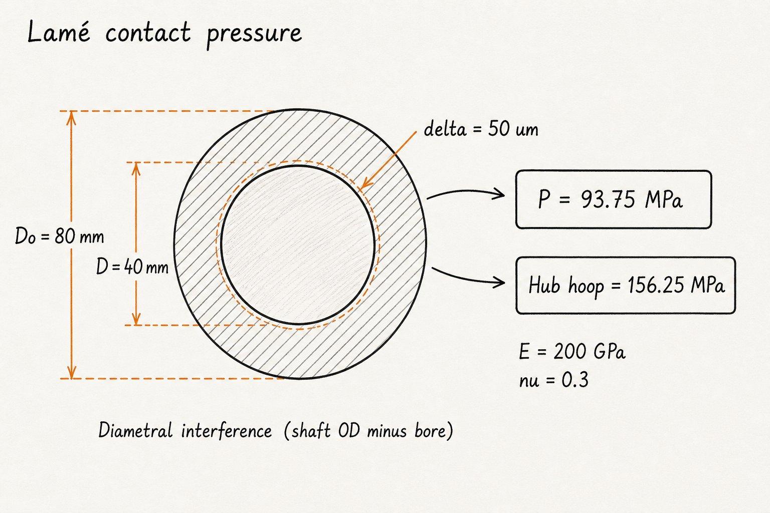
The sketch matches the default CALCULATE path: diametral δ = 50 µm on a 40 mm interface inside an 80 mm steel hub.
Contact pressure is 93.75 MPa and hub hoop stress is 156.25 MPa before you look at friction torque or press force.
Contact length L is a real shop dimension
Press-fit guides treat engagement length as an input. Older builds assumed L = 2×D as a placeholder. A short hub boss is not two diameters long.
Enter the axial length that actually carries uniform pressure. Torque scales with L. So does the force your press must deliver: F = µ P π D L. Lubrication lowers µ and can cut press force, but it also lowers torque capacity after assembly unless the film is gone in service.
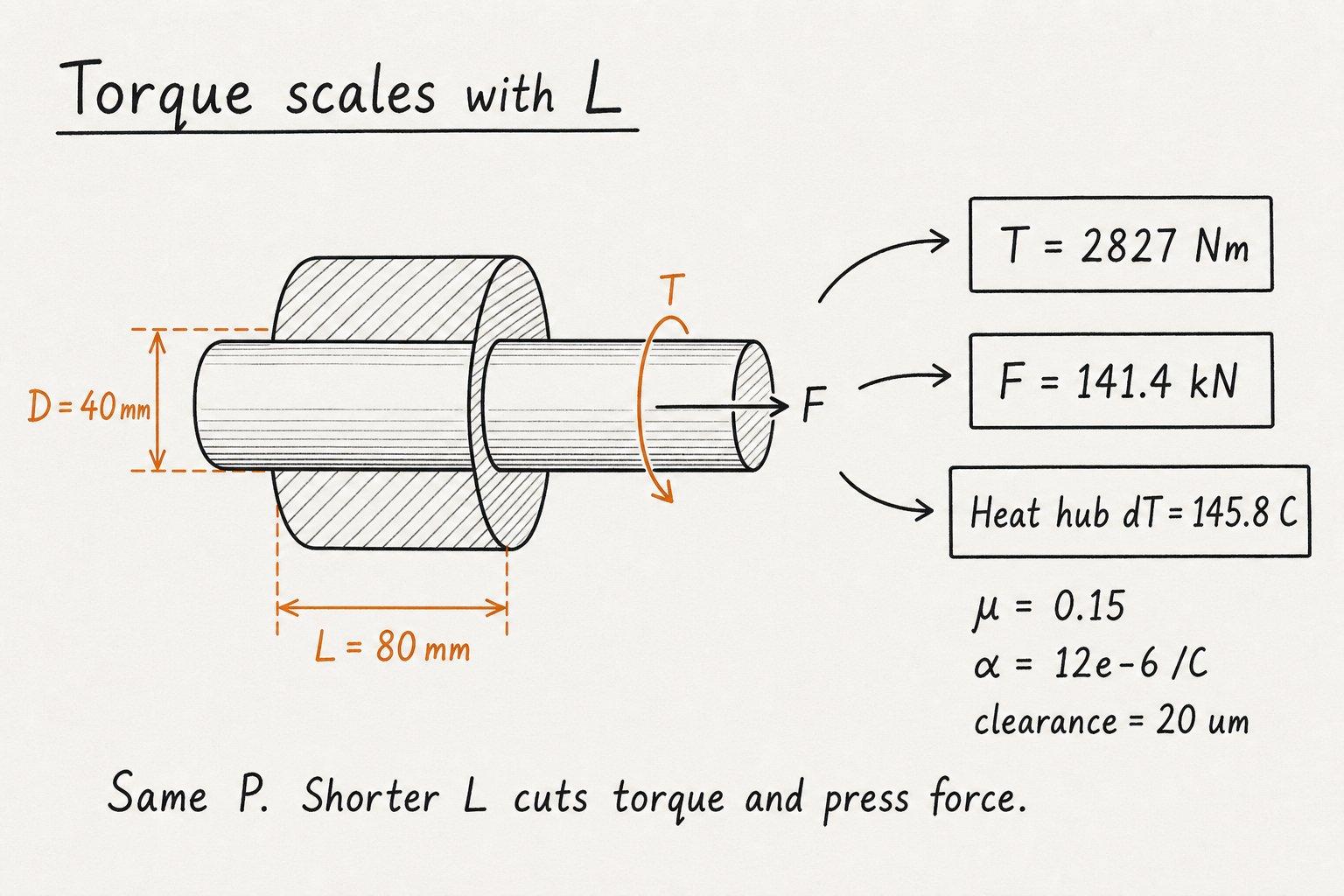
Engagement length L = 80 mm at the default pressure gives torque about 2827 N·m and assembly force about 141.4 kN.
With α = 12×10⁻⁶/°C and 20 µm assembly clearance, hub heat ΔT is about 145.8 °C. Halve L and torque and force both halve; P stays the same.
ISO 286 picks the fit class. Lamé checks the stress.
ISO 286 fit tools return clearance or interference bands for codes such as H7/p6 or H7/s6. That is tolerance geometry, not contact pressure. Once you know min and max δ from the chart, run this pad at both ends of the band.
Typical light press classes sit near a few hundredths of a millimeter on small shafts. Heavy press and shrink classes go deeper. Always check hub von Mises against yield. Defaults show hub SF ≈ 1.14 on Sy = 250 MPa, which is thin for production. Raise Do, cut δ, or use a stronger hub before you ship a drawing.
Fit class vs this pad (qualitative):
| ISO example | Role | What to do here |
|---|---|---|
| H7/p6 | Light press | Small δ, check press force |
| H7/r6 or s6 | Medium / heavy press | Check hub SF and torque |
| H7/u6 class | Heavy shrink | Use ΔT fields, watch yield |
Press at room temperature or shrink with heat
Press fit means axial force at room temperature. Shrink fit means you create temporary clearance with heat on the hub or cold on the shaft, slide parts together, then let temperatures equalize so interference returns. Large δ or large D often makes room-temperature press force impractical.
This pad estimates ΔT so α × D × ΔT covers interference plus the clearance you want for assembly. It is a first-pass thermal size change, not a furnace recipe. Soak time, gradients, and temper colors stay on the shop procedure.
Worked example
Default steel path: δ = 50 µm diametral, D = 40 mm, Do = 80 mm, Di = 0, L = 80 mm, E = 200 GPa, ν = 0.3, µ = 0.15, Sy = 250 MPa, α = 12×10⁻⁶/°C, clearance = 20 µm. Reproduce on CALCULATE.
- Leave shaft and hub on Steel. Confirm δ 50, D 40, Do 80, Di 0, L 80, µ 0.15.
- CALCULATE. P = δ / [D (Cₛ + Cₕ)] = 93.75 MPa.
- Hub hoop = P × (Do² + D²)/(Do² − D²) = 156.25 MPa. Hub von Mises = 218.75 MPa.
- T = µ P π D² L / 2 ≈ 2827 N·m. F = µ P π D L ≈ 141.4 kN.
- Hub SF = 250 / 218.75 ≈ 1.14. Heat hub ΔT ≈ (50 + 20) / (12e-6 × 40 × 1000) ≈ 145.8 °C.
Result: Contact pressure 93.75 MPa, torque ≈ 2827 N·m, assembly force ≈ 141.4 kN, hub heat ΔT ≈ 145.8 °C.
When to use
- Checking hub stress before you lock an interference on a gear or coupling hub
- Estimating friction torque capacity of a press or shrink joint
- Sizing press force for a known L, µ, and δ
- First-pass hub heat or shaft cool ΔT for shrink assembly
- Comparing steel, aluminium, brass, cast iron, or titanium presets
Limitations
- Elastic Lamé model only. No plastic press-fit, fretting fatigue, or FEA edge effects.
- Assumes concentric cylinders, uniform pressure along L, and open ends (plane-stress style).
- No centrifugal stress at speed, no Poisson recovery from axial load, no Kt stress raisers.
- ISO 286 fit codes are not selected here. Bring δ from a tolerance chart or ISO 286 limits tool.
- Shrink ΔT ignores soak, gradients, and furnace practice. α is a single linear coefficient.
- Friction µ is an input. Lubricated assembly and dry service can disagree.
- Not a substitute for a signed press-fit or shrink-fit procedure on safety-critical joints.
FAQ
- Is interference diametral or radial?
- Diametral on this pad: shaft OD minus hub bore in µm. Radial interference is half that. The old FAQ wording was wrong; do not enter radial values or every stress will be off by about 2×.
- Why did contact length become an input?
- Torque and press force scale with engagement length. Assuming L = 2×D hid short bosses and long hubs. Enter the real press length.
- What friction coefficient should I use?
- Dry steel-on-steel often sits near 0.10 to 0.20. Lubricated press can drop toward 0.05 to 0.10. Use measured or catalog values for your finish and lube state.
- Does ISO 286 give contact pressure?
- No. ISO 286 gives size deviations and interference or clearance bands. Pressure needs geometry, E, and Poisson in a Lamé (or FEA) model.
- Press fit vs shrink fit on this pad?
- Same stress model after assembly. Press fit cares about assembly force at room temperature. Shrink fit adds ΔT so you can assemble with clearance, then recover interference on cool-down.
- What safety factor is enough?
- Many shops want hub SF well above 1.5 on yield for general duty. The default path is only about 1.14 on Sy = 250 MPa so you can see a thin case. Raise Do, cut δ, or raise Sy before production.
- Can shaft and hub be different metals?
- Yes. Separate E, Poisson, yield, and α fields (or different presets) are supported. Steel shaft in aluminium hub is a common pairing.
- What does shaft bore Di change?
- Di = 0 is a solid shaft. A hollow bore makes the shaft more compliant, so the same δ produces lower contact pressure. Defaults use Di = 0; try Di = 20 mm on the 40 mm interface to see P drop from 93.75 MPa to 75 MPa.
Wire Rope Load Calculator
Wire rope SWL and sling capacity from diameter and construction, plus rope mass and reel/drum capacity screens.
Open calculatorBolt Torque Calculator
Tightening torque or clamp load from T = K × F × d. Metric sizes, property class % proof, and reverse torque mode.
Open calculatorSafety Factor Calculator
Factor of safety from strength ÷ stress. Yield or ultimate basis, material presets, and reverse solve modes.
Open calculator