CALCULATE to animate the Rankine loop
- Thermal Efficiency
- n/a%
- Net Work
- n/akJ/kg
- Turbine Work
- n/akJ/kg
- Pump Work
- n/akJ/kg
- Heat Input
- n/akJ/kg
- Heat Rejection
- n/akJ/kg
- Back Work Ratio
- n/a%
- Turbine Exit Quality
- n/a
- Net Power
- n/a
- Isentropic Exit Quality
- n/a
Before you lock boiler pressure or accept a homework steam table solution, check what the simple Rankine loop actually returns for thermal efficiency, net work, heat rejection, and turbine exit quality. This pad covers the closed steam power cycle used in fossil, nuclear secondary, and many heat-recovery plants.
Use Plant conditions when you know turbine inlet temperature and pressure, condenser pressure, and isentropic efficiencies. Switch to Steam-table enthalpies when you already have h₁–h₄ from tables, software, or a DCS historian. Optional mass flow converts net work into kilowatts. Math stays in your browser.
It lives under Thermal & Fluids Calculators. After you size condenser heat rejection, the heat exchanger LMTD calculator helps sketch cooling-side area. Conduction checks for walls and insulation sit on the heat transfer calculator.
Formula
- Standard states: 1 pump inlet · 2 boiler inlet · 3 turbine inlet · 4 turbine exit.
- Plant mode: estimate h₃ from sat. table + Cp≈2.05×ΔT_superheat; h₄s from s₃=s₄s; w_t=η_t(h₃−h₄s); w_p=v_f(P₃−P₁)/η_p; h₂=h₁+w_p; h₄=h₃−w_t.
- Enthalpy mode: w_t=h₃−h₄, w_p=h₂−h₁, q_in=h₃−h₂, q_out=h₄−h₁ (your table values).
- η_th = w_net / q_in with w_net = w_t − w_p. BWR = w_p / w_t. Exit quality x₄ = (h₄ − h_f)/h_fg when wet.
- Optional: Ẇ_net = ṁ × w_net. Plant mode also shows Carnot ceiling 1 − T_cold/T_hot (K).
Default Plant conditions path (500 °C, 3000 kPa, condenser 10 kPa, η_t=85%, η_p=90%):
| Quantity | Value |
|---|---|
| Thermal efficiency η_th | 29.94% |
| Net work w_net | 944.1 kJ/kg |
| Turbine / pump work | 947.5 / 3.36 kJ/kg |
| Heat input / rejection | 3153.4 / 2209.3 kJ/kg |
| Actual exit quality x₄ | 0.923 |
| Isentropic exit quality x₄s | 0.853 |
| Back work ratio | 0.35% |
| Carnot ceiling (T_in / T_sat,cond) | 58.7% |
How it works
Choose Plant conditions to estimate steam states from turbine inlet T/P, condenser pressure, and isentropic efficiencies, or paste steam-table enthalpies for states 1–4. The pad returns work and heat terms, thermal efficiency, back-work ratio, exit quality, optional net power, and a Carnot ceiling in plant mode.
Choose Plant conditions or Steam-table enthalpies. In plant mode enter turbine inlet °C and kPa, condenser kPa, and turbine/pump isentropic efficiencies (%). Inlet temperature must be at or above saturation at the boiler pressure. In enthalpy mode enter h₁–h₄ (kJ/kg) and optional hf, hfg for quality. Optional mass flow (kg/s) fills Net Power. CALCULATE fills Results and animates the loop sketch. Editing a field or switching modes clears Results. RESET restores the plant defaults and textbook enthalpy example values.
Plant conditions vs steam-table enthalpies
Plant mode is the screening path when you only know boiler and condenser setpoints. The pad interpolates a compact saturation table, adds a constant-Cp superheat estimate, then applies your turbine and pump isentropic efficiencies. That is enough for first-pass η_th and moisture checks, not for a guaranteed heat balance.
Enthalpy mode matches the workflow of enthalpy-first spreadsheets: paste h₁–h₄ and compute w_t, w_p, q_in, and η_th directly. Use it when IAPWS/NIST tables or trusted property software already gave you the states. For property reference see NIST Chemistry WebBook fluid properties or a printed steam table.
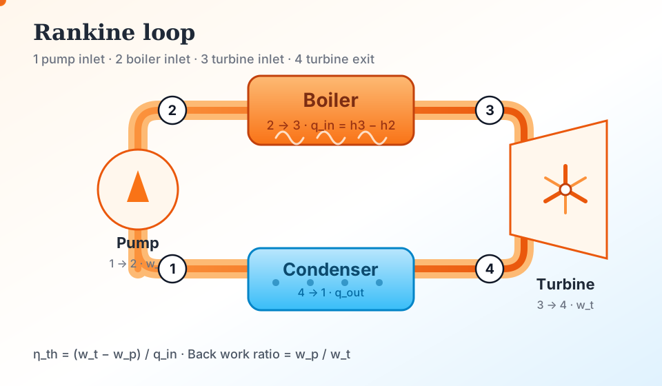
The sketch uses textbook numbering: pump 1→2, boiler 2→3, turbine 3→4, condenser 4→1 on a closed working-fluid loop.
On the Plant defaults after CALCULATE, Results show η_th ≈ 29.94% with w_net ≈ 944.1 kJ/kg, matching the Formula table. The Results diagram animates the same loop.
Why exit quality matters more than a pretty efficiency
As steam expands, it often crosses into the two-phase dome. Quality x₄ is the vapor mass fraction at the turbine exit. Droplets travel with less ability to follow blade curvature, so wet steam erodes LP blade leading edges.
This pad reports actual exit quality in both modes (from estimated h₄ in plant mode, or from your h₄ with optional hf/hfg in enthalpy mode). Values below 0.88 raise a wet caution. That threshold is shop practice, not a code absolute. Reheat, moisture separators, and higher condenser pressure are the usual cures.
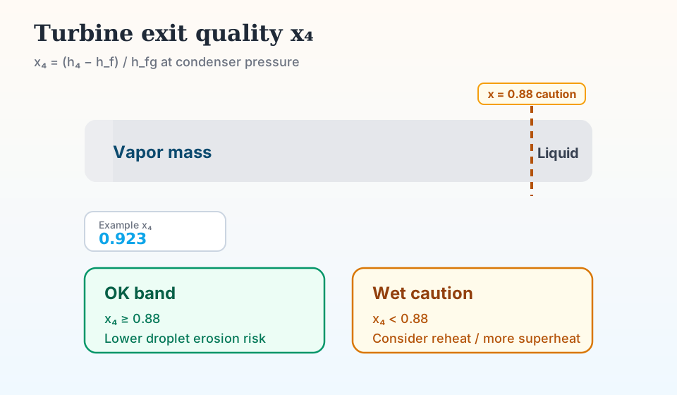
x₄ = (h₄ − hf) / hfg at condenser pressure. The dashed mark is the 0.88 caution used by this UI.
Default plant path lands near x₄ ≈ 0.923 (OK). The ideal isentropic exit is wetter (x₄s ≈ 0.853) because real turbines leave more enthalpy in the exhaust.
Back work ratio and the liquid-pump advantage
Back work ratio is pump work divided by turbine work. On the plant defaults it is about 0.35%. Steam plants stay efficient partly because you pump a nearly incompressible liquid instead of compressing a gas.
Gas-turbine Brayton loops often spend 40–50% of turbine output on the compressor. That contrast is why combined-cycle plants put a Rankine bottoming loop on HRSG steam. Use BWR here as a sanity check: if pump work looks like tens of percent of turbine work, your enthalpies or pressures are probably inconsistent.
Carnot ceiling vs real Rankine η_th
Plant mode also prints a Carnot ceiling using turbine inlet temperature and condenser saturation temperature as the hot and cold reservoirs. Real Rankine efficiency is lower because heat is not added isothermally at T_hot. Background on the cycle layout lives on Wikipedia’s Rankine cycle page. Treat that as context. Your steam table and component efficiencies still set the numbers.
On the defaults, Carnot is near 59% while the pad’s η_th is near 30%. Closing that gap in a real plant means higher boiler pressure, more superheat, reheat, and feedwater heaters. Those features are outside this simple four-state model.
What this calculator is not
It is not a reheat or regenerative plant model, not an organic Rankine (ORC) fluid library, and not a full IAPWS-95 property server. Dense steam-table solvers and property packages can go deeper on states. This page sits between a full property server and a bare enthalpy paste-in: plant screening plus enthalpy homework in one browser pad.
Do not use the Cp-superheat estimate for supercritical design, blade-life sign-off, or contractual heat-rate guarantees. Switch to Steam-table enthalpies with trusted property data, or use a full IAPWS package, when stakes rise.
Worked example
Plant conditions defaults: turbine inlet 500 °C at 3000 kPa, condenser 10 kPa, η_t = 85%, η_p = 90%, no mass flow.
- Leave Plant conditions selected. Confirm 500, 3000, 10, 85, 90. Leave Mass flow blank.
- CALCULATE. The pad estimates h₃ ≈ 3349 kJ/kg, expands isentropically to x₄s ≈ 0.853, then applies 85% turbine efficiency.
- Actual w_t ≈ 947.5 kJ/kg so h₄ ≈ 2401 kJ/kg and actual x₄ ≈ 0.923.
- Pump work ≈ 3.36 kJ/kg. Heat input ≈ 3153 kJ/kg. η_th ≈ 29.94%. BWR ≈ 0.35%.
- Optional check: switch to Steam-table enthalpies, load h₁=191.8, h₂=192.5, h₃=3230.9, h₄=2325.8, CALCULATE again. η_th ≈ 29.77% with w_net ≈ 904.4 kJ/kg.
Result: Plant defaults: η_th 29.94%, w_net 944.1 kJ/kg, x₄ 0.923 (OK). Enthalpy example: η_th 29.77%, w_net 904.4 kJ/kg.
When to use
- Screening steam-cycle efficiency from boiler and condenser setpoints
- Checking homework or DCS enthalpies for η_th, BWR, and exit quality
- Estimating condenser heat rejection before cooling-system sketches
- Converting net work to power with a known steam mass flow
Limitations
- Plant-mode steam properties use an interpolated saturation table plus Cp ≈ 2.05 kJ/kg·K of superheat, not full IAPWS/NIST accuracy.
- Plant mode requires turbine inlet temperature at or above saturation at boiler pressure. Wet or compressed-liquid inlet states are out of scope.
- No reheat, regeneration, extraction heaters, or supercritical property path.
- Not an organic Rankine cycle fluid library.
- Exit-quality caution at 0.88 is a teaching threshold. OEM blade limits may differ.
- Carnot ceiling uses T_turbine_in and T_sat,condenser only. It is not a plant heat-rate guarantee.
FAQ
- Plant conditions or steam-table enthalpies?
- Use Plant conditions when you know T, P, and component efficiencies. Use Steam-table enthalpies when you already have h₁–h₄ from tables or software. Both return η_th, work, heat, and BWR on this UI.
- Why is actual exit quality higher than isentropic quality?
- A real turbine extracts less work than the ideal expansion, so exhaust enthalpy stays higher and the mixture is drier. Plant mode shows both x₄ (actual) and x₄s (isentropic).
- What does Wet caution mean?
- Actual turbine exit quality is below 0.88. Moisture erosion risk rises. Raise superheat, add reheat, or revisit condenser pressure before treating the design as final.
- How do I get net power in kW?
- Enter Mass flow rate in kg/s. Net power = ṁ × w_net. Leave mass flow blank if you only need specific work (kJ/kg).
- Why is Rankine efficiency far below Carnot here?
- Carnot assumes isothermal heat addition at the hot temperature. Rankine adds heat while the fluid heats, boils, and superheats, so the average heat-addition temperature is lower. The gap is expected on a simple cycle.
- Can I model reheat or ORC fluids?
- No. This pad is a simple four-state water/steam Rankine screener. Reheat, regenerative feedwater heating, and organic fluids need a dedicated cycle model or property package.
- Why does plant mode reject my turbine inlet temperature?
- The superheat model needs T at or above saturation at the boiler pressure. At 3000 kPa that is about 234 °C. Raise temperature or lower pressure, or paste enthalpies in Steam-table mode.
Heat Exchanger LMTD Calculator
LMTD, heat duty, required area, and UA for counterflow or parallel flow.
Open calculatorHeat Transfer Calculator (Conduction)
Conduction heat rate, thermal resistance, and heat flux through a plane wall.
Open calculatorPipe Flow Pressure Drop Calculator
Darcy–Weisbach or Hazen–Williams pressure drop with fittings K, elevation, Reynolds number, and friction factor.
Open calculator