- Reynolds number
- —
- Laminar limit
- —
- Characteristic length
- —
- Velocity used
- —
- Kinematic viscosity
- —
- Re per metre
- —
You need to know whether a liquid or gas flow is laminar, transitional, or turbulent before you pick a friction factor, heat-transfer correlation, or wind-tunnel scale. This pad takes velocity (or pipe/duct flow rate), characteristic length, and either kinematic viscosity or density plus dynamic viscosity, then returns Reynolds number, regime, and geometry-specific limits.
Defaults open on Metric pipe flow: 2 m/s through a 50 mm ID with water at 20 °C (ν = 1.004 ×10⁻⁶ m²/s). CALCULATE returns Re ≈ 99 600 — fully turbulent. Switch to Imperial, flat plate, sphere, or rectangular duct when that matches your problem. Math stays in your browser.
It lives under Thermal & Fluids Calculators. After you know the regime, estimate friction ΔP on the pipe flow pressure drop calculator. Paste total head into the pump power calculator when you are sizing a driver.
Formula
- Re = V L / ν = ρ V L / μ with ν = μ / ρ.
- Characteristic length L: pipe → internal diameter D; rectangular duct → Dh = 2ab/(a+b); flat plate → length from leading edge; sphere/cylinder → diameter.
- Pipe / duct screening: laminar Re < 2300, transitional 2300–4000, turbulent Re ≥ 4000.
- Flat plate screening: Re_c ≈ 5×10⁵. Sphere: creep/Stokes band near Re ≪ 1; transitional toward Re ≈ 1000.
- Kinematic ν is entered as ×10⁻⁶ m²/s (water ≈ 1.004). Dynamic path uses μ in cP and ρ in kg/m³.
- Optional pipe/duct flow rate: V = Q / A with A = πD²/4 or width×height.
Default Metric pipe path (50 mm · 2 m/s · water ν = 1.004 ×10⁻⁶ m²/s):
| Quantity | Value |
|---|---|
| Reynolds number Re | ≈ 99 602 |
| Flow regime | Turbulent |
| Laminar limit | 2300 |
| Turbulent from | 4000 |
| Characteristic length | 50 mm |
| Re per metre | ≈ 1.992×10⁶ 1/m |
How it works
Compute Re = V L / ν or ρ V L / μ and classify laminar, transitional, or turbulent flow. Supports circular pipe, rectangular duct (hydraulic diameter), flat plate, and sphere/cylinder. Metric and Imperial, fluid presets, velocity or flow-rate input. Use before picking friction factor or heat-transfer correlations.
Pick Metric or Imperial, then kinematic ν or dynamic μ+ρ. Choose geometry (pipe, flat plate, sphere/cylinder, rectangular duct) and a fluid preset. For pipes and ducts you can enter velocity or volumetric flow rate. CALCULATE fills Re, regime, limits, characteristic length, and Re per metre and updates the sketch. Editing a field or switching units/modes clears Results. RESET restores defaults for the active unit system and returns geometry to pipe with kinematic viscosity.
What Reynolds number means
Reynolds number is the ratio of inertial forces to viscous forces. Low Re means viscosity keeps the motion orderly (laminar). High Re means inertia wins and the flow breaks into eddies (turbulent). The number is dimensionless, so the same Re means dynamically similar flow even when fluid, size, and speed differ — the reason wind-tunnel models try to match full-scale Re.
For circular pipes the common screening band is Re < 2300 laminar and Re ≥ 4000 turbulent, with a transitional zone between. Those limits are not physical constants; roughness, inlet shape, and vibration can move transition. This pad reports the usual textbook screening values for each geometry.
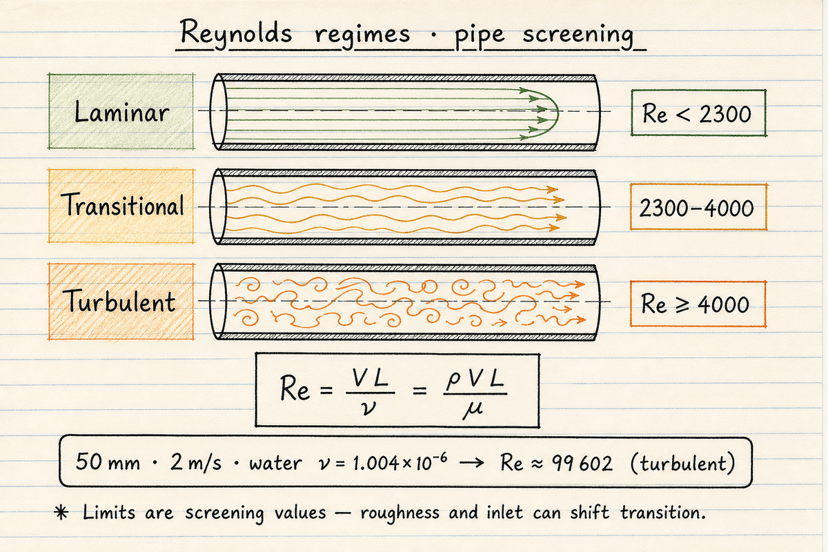
Re = V L / ν = ρ V L / μ.
Default keep-alive: 50 mm · 2 m/s water → Re ≈ 99 600 (turbulent).
Kinematic ν vs dynamic μ and density
When your data sheet gives kinematic viscosity, use the ν path. When you have dynamic viscosity and density separately (common in process and biomedical work), use μ + ρ. Both paths compute the same Re; the pad keeps ν = μ/ρ consistent behind the scenes.
Temperature matters. Liquid viscosity usually falls as temperature rises, so Re tends to increase. Gas viscosity rises with temperature, so Re tends to fall. Always use properties at the operating temperature, not a room-temperature default.
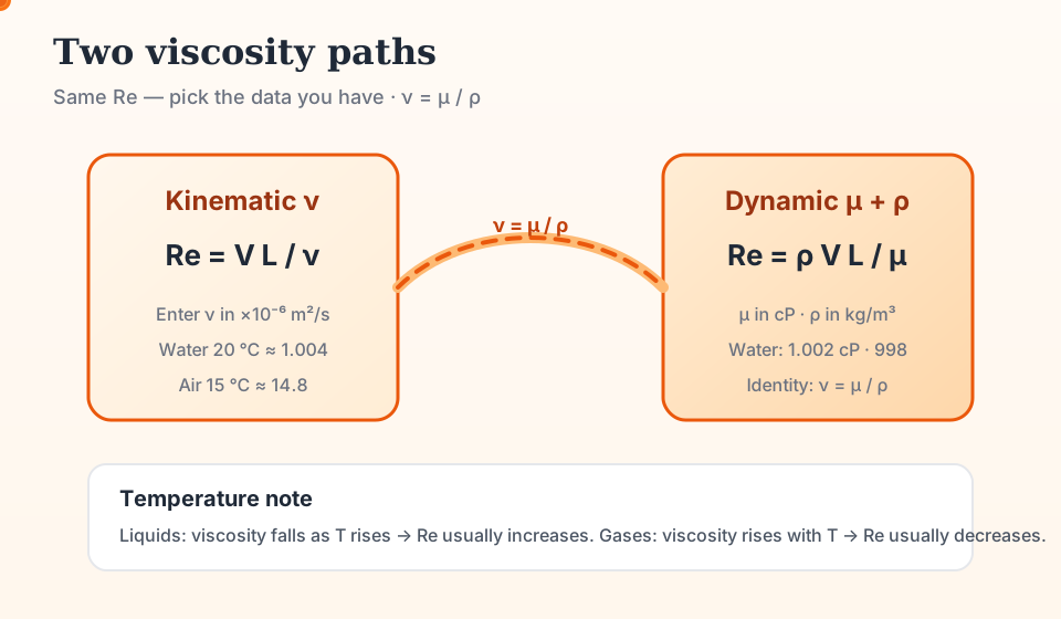
ν path: enter ×10⁻⁶ m²/s (water 20 °C ≈ 1.004).
μ + ρ path: cP and kg/m³ with ν = μ/ρ.
Choosing the characteristic length
Wrong L is the most common Re mistake. Internal pipe flow uses inside diameter. Non-circular ducts use hydraulic diameter Dh = 4A/P (for a full rectangular duct, Dh = 2ab/(a+b)). External flat plates use distance from the leading edge. Spheres and cylinders use diameter. Airfoils use chord — enter that length under flat-plate or custom length thinking.
Once you know the regime for a pipe, move to the pipe flow pressure drop calculator for Darcy or Hazen–Williams head. This pad does not compute friction factor or ΔP itself.
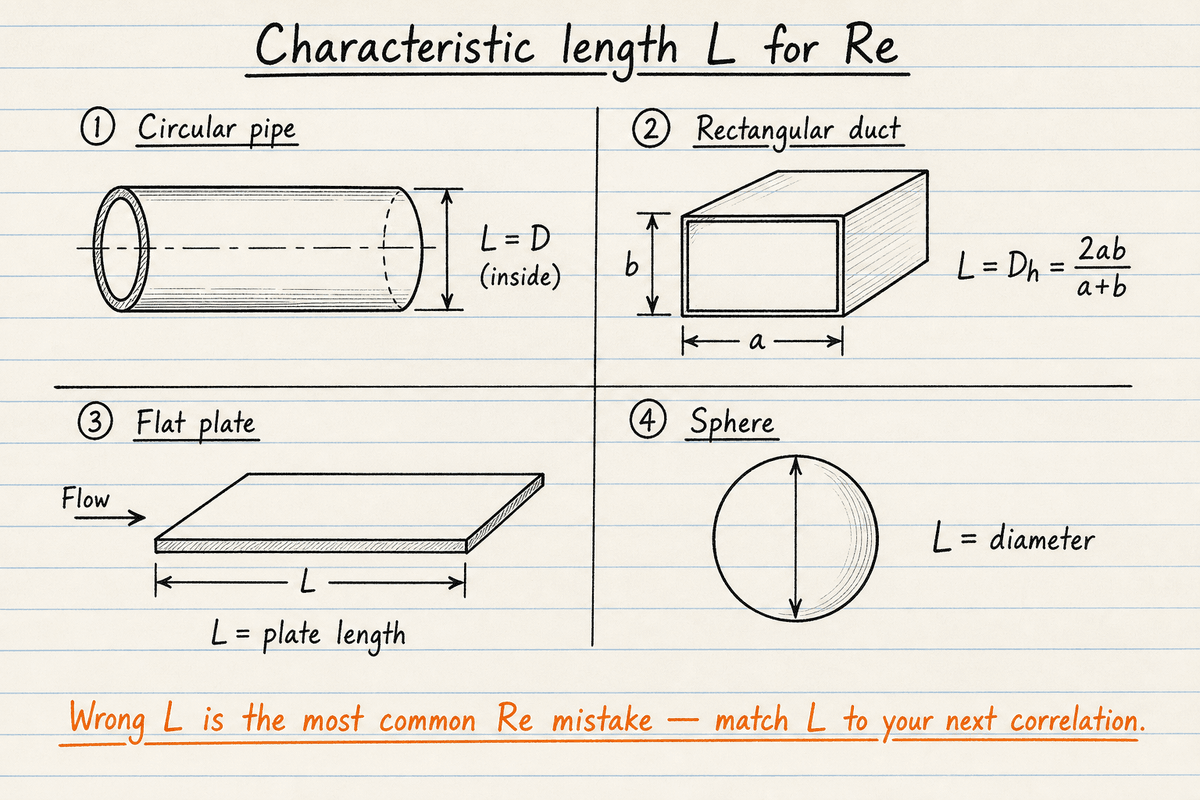
Pipe → D · Duct → Dh = 2ab/(a+b) · Plate → length from leading edge · Sphere → diameter.
Match L to the correlation you will use next — friction factors and Nu correlations assume a specific definition.
Worked example
Metric pipe default: water at 20 °C (ν = 1.004 ×10⁻⁶ m²/s) at 2 m/s in a 50 mm ID pipe.
- L = D = 0.05 m
- Re = V L / ν = 2 × 0.05 / (1.004×10⁻⁶) ≈ 99 602
- 99 602 ≫ 4000 → turbulent pipe flow
- Same duty with μ = 1.002 cP and ρ = 998 kg/m³: Re = ρ V D / μ ≈ 99 600
Result: Re ≈ 99 600, turbulent. AJ Designer check: 1.5 m/s · 50 mm · ρ 998 · μ 0.001002 Pa·s → Re ≈ 74 700 (also turbulent).
When to use
- Classifying pipe or duct flow before picking a friction factor
- Checking laminar vs turbulent heat-transfer correlations
- Flat-plate or sphere/cylinder external-flow screening
- Matching wind-tunnel or scale-model Reynolds number
Limitations
- Transition limits are engineering screening values, not hard physics constants
- Newtonian fluids only — no Metzner–Reed / power-law Re
- No full ISA atmosphere table (use an air preset or enter ν at altitude)
- Does not compute friction factor, pressure drop, or drag coefficient
- Pipe-flow pad uses Re ≤ 2000 for laminar f = 64/Re; this pad’s regime label uses 2300/4000
- No reverse-solve for every variable (velocity-from-Re deferred)
FAQ
- Why is kinematic viscosity in ×10⁻⁶ m²/s?
- Water at about 20 °C has ν ≈ 1.0×10⁻⁶ m²/s. Entering 1.004 is easier than typing 0.000001004. Air at 15 °C is about 14.8 on the same scale. Switch to the μ + ρ path if that matches your data sheet.
- At what Reynolds number does pipe flow become turbulent?
- For circular pipes this pad treats Re < 2300 as laminar, 2300–4000 as transitional, and Re ≥ 4000 as turbulent. Real transition depends on roughness and disturbances; treat the band as approximate.
- What characteristic length should I use?
- Pipe: inside diameter. Rectangular duct: hydraulic diameter (computed for you). Flat plate: length from the leading edge. Sphere or cylinder: diameter. Matching L to the correlation you will use later is essential.
- How do I use this with the pipe-flow calculator?
- Confirm the regime here, then open the pipe flow pressure drop calculator with the same D, V (or Q), and fluid properties to get friction head and ΔP. Pump motor sizing from that head belongs on the pump power calculator.
- Does Reynolds number apply to gases?
- Yes. Air, steam, and other gases use the same formulas. Pick an air preset or enter ν (or μ and ρ) at your temperature and pressure. Compressible effects need Mach number separately — this pad stays on viscous similarity.
Pipe Flow Pressure Drop Calculator
Darcy–Weisbach or Hazen–Williams pressure drop with fittings K, elevation, Reynolds number, and friction factor.
Open calculatorPump Power Calculator
Hydraulic, shaft, and electrical pump power from flow, head or pressure, density, and efficiencies.
Open calculatorHeat Exchanger LMTD Calculator
LMTD, heat duty, required area, and UA for counterflow or parallel flow.
Open calculator