You need a minimum shaft diameter that survives torsion, bending, or both, without pretending to be a full multi-bearing FEA. This pad covers six design bases: torque only, bending only, combined static (Guest Te + Rankine Me), ASME fluctuating with Km/Kt shock factors, torsional rigidity from a twist limit, and a check of an existing diameter. Solid or hollow (k = di/do), torque from direct entry or from power and RPM, ASME material allowables or manual τ/σ, and an optional keyway −25%.
Defaults open on ASME / fluctuating: T = 150 N·m, M = 200 N·m, Structural Steel A36, FOS 2, steady Km = 1.5 / Kt = 1.0. CALCULATE returns Te ≈ 335 N·m, τallow = 36 MPa, required d ≈ 36.2 mm, and stock 38 mm. Switch to the torsion preset (20 kW @ 200 rpm, τ = 42 MPa) for the pure-torsion example d ≈ 48.7 mm. Math stays in your browser.
It sits under Mechanical Calculators next to the shaft diameter calculator (pure torsion quick size), keyway calculator, and critical speed calculator. Multi-bearing FEA and reaction solvers are out of scope.
Formula
- Torque from power: T (N·m) = 60·P_W / (2π·N) = 9550·P_kW / N.
- Solid torsion: d³ = 16T / (π τ). Hollow: multiply the section by (1−k⁴) with k = di/do.
- Solid bending: d³ = 32M / (π σ). Hollow uses the same (1−k⁴) factor.
- Guest: Te = √(M²+T²) = (π/16) τ d³ (1−k⁴). Rankine: Me = ½[M+√(M²+T²)] = (π/32) σ d³ (1−k⁴). Combined static takes the larger d.
- ASME fluctuating: Te = √((Km·M)²+(Kt·T)²). τallow = min(0.18 Sut, 0.3 Sy) / FOS; keyway × 0.75.
- Torsional rigidity: T/J = Gθ/L with J = (π/32) d⁴ (1−k⁴).
- Check mode: σb = 32M/(π d³), τ = 16T/(π d³), von Mises = √(σb²+3τ²), Tresca = √(σb²+4τ²).
Reproduce the default ASME combined path on CALCULATE:
| Quantity | Value |
|---|---|
| Inputs | T = 150 N·m · M = 200 N·m · A36 · FOS 2 · Km 1.5 · Kt 1.0 |
| τallow | min(0.18×400, 0.3×250)/2 = 36 MPa |
| Te | ≈ 335.4 N·m |
| Required d | ≈ 36.2 mm |
| Stock size | 38 mm |
How it works
Six design bases: torque only, bending only, combined static (Guest Te + Rankine Me), ASME fluctuating with Km/Kt, torsional rigidity, and check existing diameter. Solid or hollow (k = di/do), power→torque, ASME material allowables or manual τ/σ, keyway −25%.
Pick Design basis (ASME default) or a Quick preset. The animated sketch switches with the basis (torsion, bending, Guest/Rankine, ASME Km/Kt, rigidity, or check existing). Choose solid/hollow, torque source, and allowable source. Enter loads (and Km/Kt or rigidity fields when shown). CALCULATE fills Results. Editing a field clears Results. RESET restores ASME T150/M200 A36 defaults.
Start from power when you only know kW and rpm
Shaft sizing tools open with T from P and N, then size on torsion or Te = √(M²+T²). ASME commercial notes often quote τ = 42 MPa with keyways (56 MPa without).
On this pad, Torque only + From power and RPM matches that path. The torsion example (20 kW @ 200 rpm, τ = 42 MPa) returns T ≈ 955 N·m and d ≈ 48.7 mm. For pure torsion without bending, the sibling shaft diameter calculator is the shorter tool; use this pad when bending, shock factors, hollow sections, or twist limits matter.
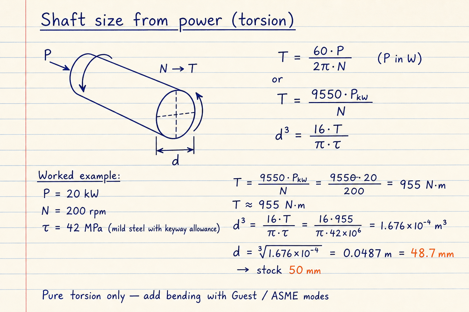
T = 9550·P/N → ≈ 955 N·m at 20 kW / 200 rpm.
d³ = 16T/(π τ) → d ≈ 48.7 mm (stock 50 mm).
ASME Km, Kt for fluctuating bending and torsion
Real shafts rarely see steady M and T. ASME shock tables raise Km and Kt for gradual, minor-shock, or heavy-shock duty. This pad’s ASME mode uses Te = √((Km·M)²+(Kt·T)²) and sizes on τallow from the material (min(0.18 Sut, 0.3 Sy)/FOS), with an optional keyway × 0.75.
Default example: T = 150 N·m, M = 200 N·m, A36, FOS 2, Km = 1.5, Kt = 1.0 → τallow = 36 MPa, Te ≈ 335 N·m, d ≈ 36.2 mm, recommend 38 mm. Combined static mode (no Km/Kt) shows both Guest and Rankine diameters and picks the larger.
Shock / fatigue factor presets on this pad:
| Duty | Km | Kt |
|---|---|---|
| Steady / gradual | 1.5 | 1.0 |
| Minor shocks | 1.5 | 1.5 |
| Heavy shocks | 2.0 | 1.5 |
| Custom | user | user |
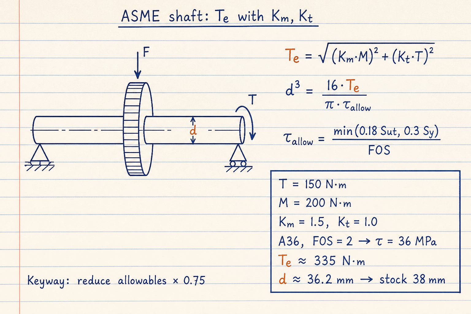
Steady duty Km = 1.5, Kt = 1.0 on M = 200 N·m, T = 150 N·m.
τallow = 36 MPa → d ≈ 36.2 mm → stock 38 mm.
Hollow shafts, rigidity, and what this pad is not
Shaft design references add hollow k = di/do, von Mises / Tresca checks, and an existing-diameter mode. This pad ships the same hollow factor (1−k⁴), Check existing diameter, and von Mises / Tresca readouts. Torsional rigidity mode follows a camshaft-style T/J = Gθ/L path.
Multi-bearing FEA shaft products solve reactions, BMDs, and stress concentrations in dedicated software. That is out of scope here. For fatigue S-N use the fatigue pad; for whirling use critical speed; for key geometry use the keyway pad.
Scope boundaries:
| In scope | Out of scope |
|---|---|
| Guest / Rankine / ASME Te sizing | Multi-bearing FEA |
| Solid + hollow k = di/do | Peterson Kt maps on shoulders |
| Power→torque + rigidity θ limit | Full fatigue S-N life |
| Check existing d + VM/Tresca | Driveshaft SKU / tube series |
Worked example
Default ASME combined: T = 150 N·m, M = 200 N·m, A36, FOS 2, Km = 1.5, Kt = 1.0. Reproduce on CALCULATE.
- Leave Quick preset on ASME combined · T 150 · M 200 · A36 (or enter the same values).
- CALCULATE → τallow = 36 MPa, Te ≈ 335 N·m, d ≈ 36.2 mm, stock 38 mm.
- Torsion example: Torque only · 20 kW @ 200 rpm · τ 42 → d ≈ 48.7 mm.
- Combined static example: T 150, M 200, τ 40, σ 125 → Guest d ≈ 31.7 mm controls.
- Rigidity example: T 955 N·m, L 1000 mm, θ 0.25°, G 80 GPa → d ≈ 72.7 mm.
Result: Default ASME: d ≈ 36.2 mm (stock 38). Torsion example ≈ 48.7 mm. Combined static Guest ≈ 31.7 mm. Rigidity ≈ 72.7 mm.
When to use
- Sizing a solid or hollow shaft for torsion, bending, or both
- Applying ASME Km/Kt shock factors before picking stock diameter
- Checking an existing diameter against σb, τ, von Mises, and Tresca
- Enforcing a torsional twist limit (camshaft / timing shafts)
- Converting motor kW and rpm into design torque before diameter sizing
Limitations
- Preliminary static / ASME commercial sizing only. Not a stamped code workbook.
- Circular shafts only. No non-round sections.
- No shoulder fillets, keyway Kt maps, or FEA stress concentrations.
- No bearing reaction solver or multi-span BMD.
- No fatigue S-N or critical-speed check (use sibling pads).
- Material Sy/Sut presets are representative. Verify against the mill cert for release.
- ASME τallow = min(0.18 Sut, 0.3 Sy) is commercial shafting practice, not every code edition.
- Grey cast iron (Sy = 0) is omitted from the material list. Use manual allowables for brittle irons.
- Keyway checkbox multiplies entered or ASME allowables by 0.75. If your manual τ already includes the keyway cut (e.g. 42 MPa), leave it unchecked.
- ASME utilization is against Te / τallow (factored), not raw unfactored τ alone.
FAQ
- What is the difference between this and the shaft diameter calculator?
- The shaft diameter calculator is the short pure-torsion path from power, rpm, and τ. This pad adds bending, Guest/Rankine, ASME Km/Kt, hollow sections, rigidity, and an existing-diameter check.
- Why show both Guest and Rankine diameters?
- Guest (maximum shear) sizes on Te and τ. Rankine (maximum normal) sizes on Me and σ. Combined static mode takes the larger of the two so neither theory is violated. ASME commercial practice on this pad sizes primarily on Te / τallow and still reports the Rankine companion d.
- What Km and Kt should I use?
- Steady or gradual rotating shafts often start at Km = 1.5, Kt = 1.0. Minor shocks raise both toward 1.5–2.0. Heavy shocks can reach Km = 2–3 and Kt = 1.5–3. Pick a preset or enter custom values in ASME mode.
- Does the keyway checkbox replace a key stress check?
- No. It only applies the ASME commercial −25% reduction on shaft allowables. Size the key itself on the keyway calculator.
- Is a multi-bearing FEA shaft tool the same job?
- No. FEA shaft tools solve multi-bearing shafts with reactions, shear/moment diagrams, and stress concentrations. This pad is closed-form diameter sizing for circular shafts.
Shaft Diameter Calculator
Quick solid or hollow shaft diameter from power/RPM or torque under pure torsion, with stock size and keyway option.
Open calculatorCritical Speed Calculator
First critical whirling speed from static sag, shaft EI geometry, or screw end-fixity, with operating-speed margin.
Open calculatorKey & Keyway Design Calculator
ANSI B17.1 / ISO 773 key lookup plus parallel-key shear and bearing stress check under torque.
Open calculatorFatigue Life Calculator
Marin-corrected endurance limit with Goodman, Soderberg, and Gerber fatigue factors of safety plus Basquin life estimate.
Open calculatorVon Mises Stress Calculator
Distortion-energy equivalent stress from plane stress, principals, or a 3D tensor, with yield check.
Open calculator