You need a quick minimum shaft diameter under pure torsion from motor power and speed, or from a known torque. This pad stays on that job: solid or hollow (k = di/do), manual τ or ASME from material, optional keyway −25% and torque-share factor, a check of an existing diameter, and an empirical B·(P/n)⅓ handbook screen. For bending, Guest/Rankine, ASME Km/Kt, or twist limits, use the full shaft design calculator.
Defaults open on From power and RPM: 10 kW at 1440 rpm, τ = 42 MPa (ASME mild steel with keyway allowance, checkbox off because τ is already adjusted). CALCULATE returns T ≈ 66.3 N·m, d ≈ 20.0 mm, and stock 22 mm. Switch to the torque preset (T = 81.9 N·m, τ = 33.3 MPa → d ≈ 23.2 mm) or the hollow torsion preset (20 kW @ 200, k = 0.6). Math stays in your browser.
It sits under Mechanical Calculators next to the shaft design calculator and keyway calculator. Use the shaft design calculator when bending or shock factors matter.
Formula
- Torque from power: T (N·m) = 9550 · P_kW / N.
- Solid torsion: d³ = 16T / (π τ). Hollow: d_o³ = 16T / (π τ (1−k⁴)), k = di/do.
- Design torque: T_design = T · share (1.0 / 0.66 / 0.50 or custom).
- ASME τallow = min(0.18 Sut, 0.3 Sy) / FOS; keyway × 0.75 when checked.
- Check mode: τ = 16T / (π d³ (1−k⁴)); T_max = π τ d³ (1−k⁴) / 16.
- Empirical screen: d = B · (P/n)⅓ with B ≈ 105–125 (not a stress proof).
Reproduce the default power path on CALCULATE:
| Quantity | Value |
|---|---|
| Inputs | P = 10 kW · N = 1440 rpm · τ = 42 MPa |
| Torque T | ≈ 66.3 N·m |
| Required d | ≈ 20.0 mm |
| Stock size | 22 mm |
| Status | Within allowables (util ≈ 100% at required d) |
How it works
Pure-torsion sizing: T from power and RPM or direct torque, d from τallow (manual or ASME), solid/hollow (k = di/do), optional keyway −25% and torque share. Check existing diameter for capacity. Empirical B·(P/n)⅓ screen included. For bending or Km/Kt use shaft design.
Pick Input mode (power default) or a Quick preset. The animated sketch switches with the mode (power, torque, check existing, or empirical B). Choose solid/hollow and allowable source (hidden on empirical — that mode is a solid B·(P/n)⅓ screen with a manual τ cross-check only). CALCULATE fills Results. Editing a field clears Results. RESET restores 10 kW @ 1440 / τ 42.
Power and RPM is the everyday path
Shaft sizing tools start from T = 9550·P/N (or direct torque) and d = ∛(16T/(π τ)). Gear-duty screens add FOS, tensile-based allowables, and a torque-share dropdown.
On this pad, From power and RPM is that path. Defaults match a common motor screen: 10 kW at 1440 rpm with τ = 42 MPa → T ≈ 66.3 N·m and d ≈ 20.0 mm (stock 22 mm). Torque share lets you apply 66% or 50% of motor torque when this shaft does not take the full load.
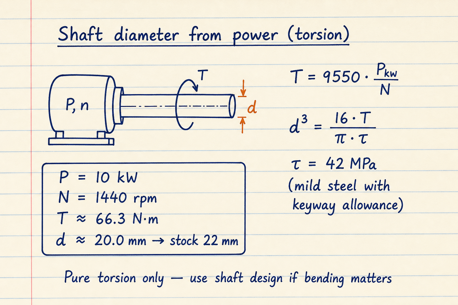
T = 9550·P/N → ≈ 66.3 N·m at 10 kW / 1440 rpm.
d³ = 16T/(π τ) → d ≈ 20.0 mm (stock 22 mm).
Hollow shafts and checking an existing diameter
Circular-shaft torsion worksheets size solid or hollow shafts with k = di/do and the (1−k⁴) polar-factor. Same physics here: for the 20 kW / 200 rpm torque (~955 N·m) and τ = 42 MPa, k = 0.6 returns do ≈ 51.0 mm and di ≈ 30.6 mm.
Check existing diameter reports τ under the applied torque, utilization vs τallow, and the max torque (and power at the entered RPM) the section can carry. Use it to decide whether a stock bar already on the shelf is enough before you redesign.
ASME commercial τallow reminders:
| Condition | Typical τ |
|---|---|
| No keyway (commercial steel) | ≈ 56 MPa |
| With keyway allowance | ≈ 42 MPa |
| Or from material | min(0.18 Sut, 0.3 Sy) / FOS |
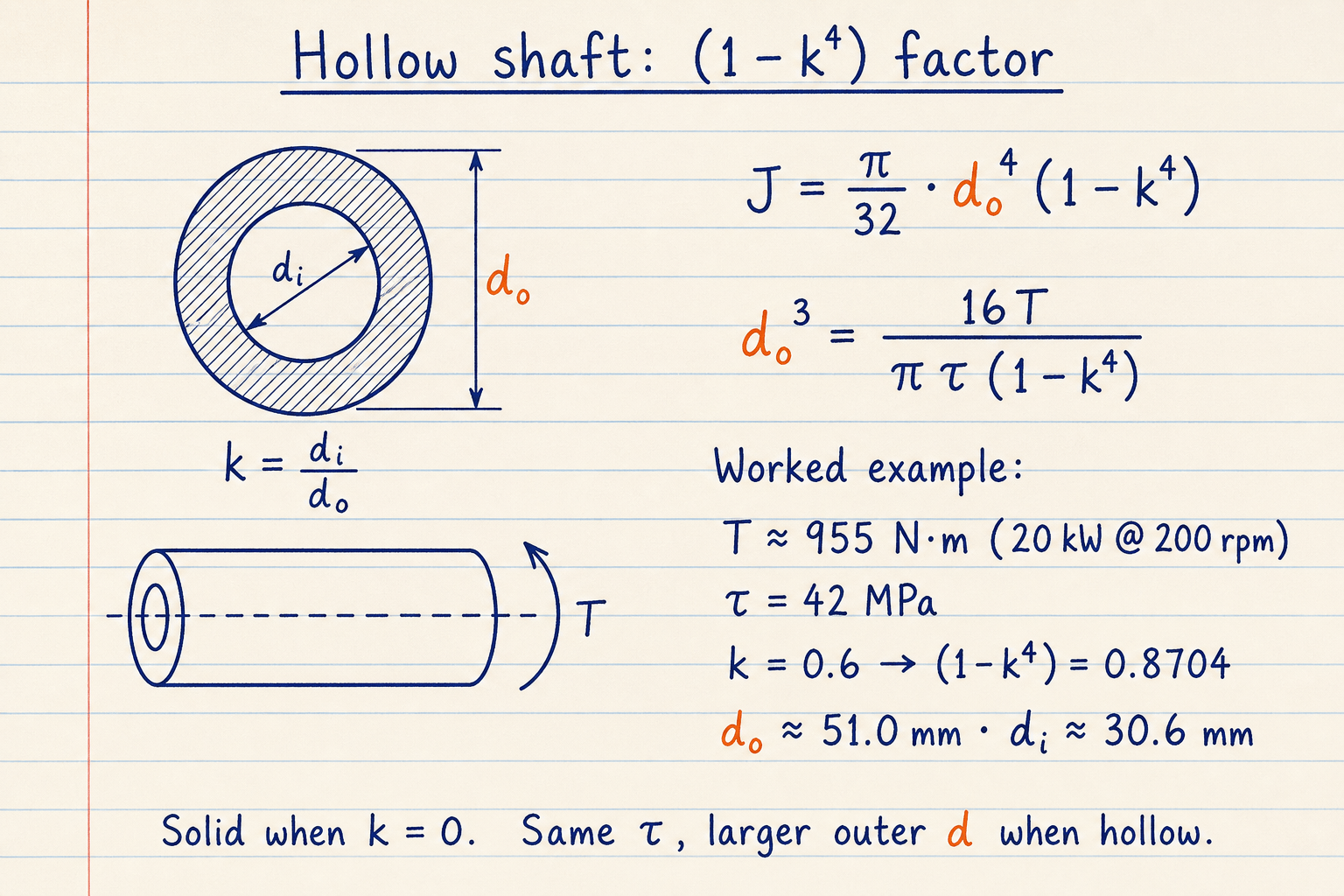
k = 0.6 → (1 − k⁴) = 0.8704.
Same T and τ as the solid torsion case → larger outer diameter.
Empirical B screen and what this pad is not
The handbook empirical d = B·(P/n)⅓ folds material and duty into B (often ~105–125 for steel in mm/kW/rpm units). This pad’s Empirical mode ships that screen and still shows a solid-shaft τ cross-check against the manual τ field. Leftover hollow, ASME, keyway, or torque-share settings from other modes are ignored here. It is not a substitute for the stress-based modes.
Not bending + torsion (use shaft design). Not optional twist-rate sizing (use shaft design torsional rigidity). Not multi-bearing FEA. Size the key on the keyway pad after you pick d.
Scope boundaries:
| In scope | Out of scope |
|---|---|
| Pure torsion d from P,N or T | ASME Km/Kt + bending |
| Solid + hollow k | Twist-rate / rigidity sizing |
| Keyway ×0.75 + stock size | Fatigue S-N / critical speed |
| Empirical B screen | Multi-span FEA |
Worked example
Default From power and RPM: 10 kW, 1440 rpm, τ = 42 MPa. Reproduce on CALCULATE.
- Leave Quick preset on Motor · 10 kW @ 1440 · τ 42 (or enter the same values).
- CALCULATE → T ≈ 66.3 N·m, d ≈ 20.0 mm, stock 22 mm.
- Torque example: From torque · T 81.9 · τ 33.33 → d ≈ 23.2 mm (stock 25).
- Hollow example: 20 kW @ 200, k = 0.6, τ 42 → do ≈ 51.0 mm.
- Empirical example: B = 105, 10 kW @ 1440 → d ≈ 20.0 mm (confirm with τ mode).
Result: Default: d ≈ 20.0 mm (stock 22). Torque preset ≈ 23.2 mm. Hollow torsion ≈ 51.0 mm OD.
When to use
- First-pass drive-shaft diameter from motor kW and rpm
- Sizing from a known torque under pure torsion
- Comparing solid vs hollow OD for the same τ limit
- Checking whether an existing bar diameter is adequate
- Running a handbook B·(P/n)⅓ screen
Limitations
- Pure torsion only. No bending moment, Km/Kt, or Guest/Rankine combined sizing.
- Circular shafts only.
- Empirical B mode is a handbook screen, not a stress proof. It always sizes a solid shaft and ignores hollow / ASME / keyway / share leftovers.
- From-torque mode does not invent capacity power from a hidden RPM. Enter RPM in Check existing (optional) or use From power and RPM.
- No twist-rate / rigidity criterion (use shaft design).
- No shoulder fillets, keyway Kt maps, or FEA.
- Material Sy/Sut presets are representative. Verify mill certs for release.
- Keyway checkbox multiplies allowables by 0.75. If manual τ is already 42 MPa with keyways, leave it unchecked.
FAQ
- When should I use shaft diameter vs shaft design?
- Use this pad for pure torsion from power/RPM or torque. Use shaft design when bending, ASME shock factors, Rankine/Guest take-the-max, or a twist limit controls the size.
- Why is recommended stock larger than required d?
- Required d is the continuous mathematical minimum. Stock rounds up to the next preferred diameter so you never undersize the bar you buy.
- What is torque share?
- When this shaft does not carry the full motor/gearbox torque (shared path or staged drive), apply 66% or 50% (or a custom factor) so design torque = T × share before sizing.
- What does coefficient B mean?
- In the empirical mode, B folds material and duty into one constant for d = B·(P/n)⅓. Typical steel screens sit near 105–125 when d is in mm, P in kW, and n in rpm. Always confirm with a τ-based mode.
- Is 42 MPa the right allowable?
- ASME commercial practice often quotes about 56 MPa without keyways and 42 MPa with keyway allowance for mild steel. Alloy shafts and precise allowables from Sy/Sut may differ. Use Manual τ or ASME from material accordingly.
Shaft Design Calculator
Minimum shaft diameter from torsion, bending, Guest/Rankine combined, ASME Km/Kt, or twist limit. Solid or hollow.
Open calculatorKey & Keyway Design Calculator
ANSI B17.1 / ISO 773 key lookup plus parallel-key shear and bearing stress check under torque.
Open calculatorMotor Gearbox Selector Calculator
Motor power from load torque, or gearbox output torque from motor power, ratio, SF, and efficiency.
Open calculatorCritical Speed Calculator
First critical whirling speed from static sag, shaft EI geometry, or screw end-fixity, with operating-speed margin.
Open calculator