You need a helical compression spring that hits a working load without slamming solid or buckling sideways. This pad takes wire size, linked mean / OD / ID coil diameters, total coils, end type, free length, load, and wire material, then returns rate, Wahl stress, solid height, pitch, and a Safe or Fail design verdict.
Defaults open on a music-wire spring: 2 mm wire, 16 mm mean coil, 12 total coils, closed and ground ends, 60 mm free length, 50 N load. That path gives about 10 active coils, 3.955 N/mm rate, 12.64 mm deflection, 24 mm solid height, and Safe on the static checks. Try F = 100 N to see Fail on stress. Switch Metric or Imperial first. Math stays in your browser.
It lives under Mechanical Calculators. After compression looks right, size an extension spring on the tension spring calculator or an angular rate on the torsion spring calculator.
Formula
- Linked coil diameters: edit any of d, Mean D, OD, or ID. OD = D + d and ID = D − d keep the others in sync.
- Active coils Na and solid height Ls follow end type (SMI-style). Closed & ground: Na = Nt − 2, Ls = Nt × d.
- Spring rate k = G × d⁴ ÷ (8 × D³ × Na). G comes from the wire material preset (MPa).
- Wahl factor Kw = (4C − 1)/(4C − 4) + 0.615/C with C = D/d. Shear stress τ = 8 × F × D × Kw ÷ (π × d³).
- Deflection δ = F/k. Max travel to solid = Lf − Ls. Force at solid = k × (Lf − Ls).
- Pitch from free length and end type. Closed & ground: p = (Lf − 2d)/Na. Buckling ratio = Lf/D.
- Safe requires index 4–12, solid clearance, pitch OK, stress ≤ 45% Sys guideline, and Lf/D ≤ 4.
Reproduce the default Closed & ground path:
| Check | Value on this pad |
|---|---|
| Inputs | d 2 mm, mean D 16 mm, Nt 12, CG, Lf 60 mm, F 50 N, music wire |
| Active coils / solid height | Na 10, Ls 24 mm |
| Spring rate / index | k ≈ 3.955 N/mm, C = 8, Kw ≈ 1.184 |
| Deflection at 50 N | ≈ 12.64 mm (under 36 mm to solid) |
| Verdict | Safe (stress ≈ 96% of 45% yield guideline) |
How it works
Use Metric or Imperial, then enter wire diameter and any of Mean D, OD, or ID. The linked fields update from OD = D + d and ID = D − d. Total coils and end type set active coils and solid height. Spring rate uses material shear modulus and mean diameter. The design verdict is Safe only when index, solid clearance, pitch, stress, and buckling checks all pass.
Pick Metric or Imperial at the top. Edit any of d, Mean D, OD, or ID and the others sync from OD = D + d and ID = D − d. The live diagram labels the active diameter and end type. Enter end type, total coils, free length, load, and material, then click CALCULATE. Results show rate, stress, solid height, pitch, design checks, and Safe/Fail. RESET restores the music-wire defaults.
Spring index and the Wahl correction
Spring index C is mean coil diameter divided by wire diameter. Shop coils usually stay between 4 and 12. Outside that band the helical spring is hard to wind or soft and tippy. This pad flags index outside 4–12.
Wahl factor Kw raises shear stress for wire curvature. At C = 8, Kw is about 1.184. Ignoring Kw understates stress on tight coils. Reproduce C = 8 and Kw on the default CALCULATE path before you change diameters.
Index band used on this pad:
| C = D/d | What it means here |
|---|---|
| Below 4 | Index check flags Above limit; hard to manufacture |
| 4 to 12 | Typical shop range; Within limit |
| Above 12 | Index check flags; watch buckling without a guide |
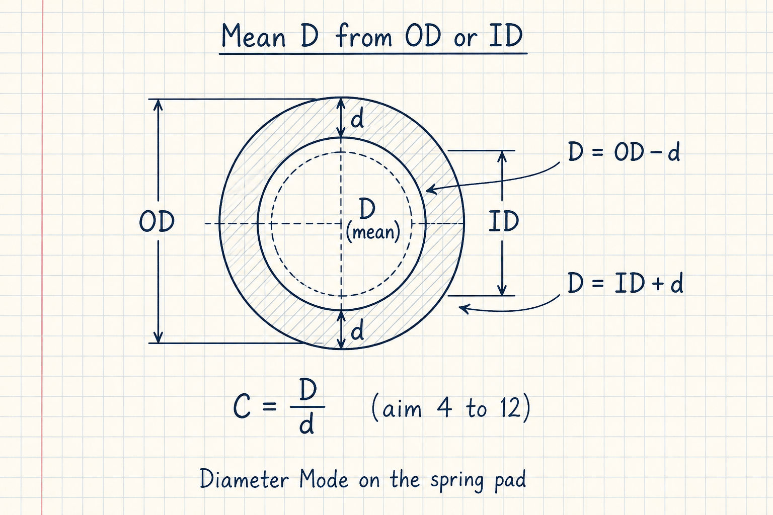
The top-view ring shows outside diameter OD, inside diameter ID, and wire thickness d. Mean diameter D sits on the wire centerline.
On this pad, edit any of d, Mean D, OD, or ID. The others sync from OD = D + d and ID = D − d. Spring index C = D/d should land between 4 and 12 for most shop coils.
End type sets active coils and solid height
You enter total coils Nt. End type decides how many coils work (Na) and how short the spring can go (solid height Ls). Closed and ground is the default because most load-bearing compression springs seat on ground ends.
Open ends keep all coils active but stack taller at solid. Closed ends remove two inactive coils from the rate formula. Match the end callout on the print before you trust Ls or max deflection. The live SVG next to the inputs updates the end-type note as you change the dropdown.
SMI-style mapping on this pad:
| End type | Active coils Na | Solid height Ls |
|---|---|---|
| Open | Nt | (Nt + 1) × d |
| Open & ground | Nt − 1 | Nt × d |
| Closed | Nt − 2 | (Nt + 1) × d |
| Closed & ground | Nt − 2 | Nt × d |
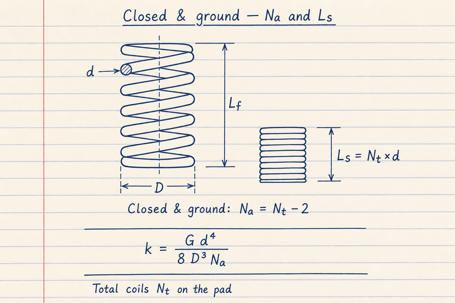
The free spring shows wire d, mean D, and free length Lf. Beside it, solid height Ls = Nt × d for closed and ground ends, with Na = Nt − 2.
That matches the default path on CALCULATE: Nt 12, Closed & ground → Na 10 and Ls 24 mm when d = 2 mm. Rate still uses Na in k = G d⁴ / (8 D³ Na).
Buckling ratio and pitch sanity
Buckling ratio is free length divided by mean coil diameter. Values above 4 on an unsupported spring often need a guide rod or a redesign. The buckling result card highlights when Lf/D exceeds 4.
Pitch is back-calculated from free length and end type. A pitch at or below zero, or larger than half the mean diameter, trips the pitch check. That usually means too few coils for the free length (steep, unstable coils) or a free length shorter than solid height.
- Solid clearance check flags when load deflection exceeds travel to solid
- Force at solid is k × (Lf − Ls); treat it as a first-pass ceiling, not a fatigue rating
- Surge frequency and cycle life are out of scope on this pad
Wire material and the 45% shear guideline
Material presets fill shear modulus G used in the compression spring rate formula. Music wire (ASTM A228) is the default at G = 81,000 MPa. Stainless 302/304 drops G to 69,000 MPa, so the same geometry is softer.
Stress / 45% Yield compares Wahl shear stress to about 45% of the material’s approximate ultimate shear for static service. Above 100% the card highlights. Fatigue and elevated temperature need a separate review with your material data.
Preset G values (MPa):
| Material | G | Approx Sys |
|---|---|---|
| Music wire (A228) | 81,000 | 700 |
| Hard-drawn | 79,500 | 560 |
| Oil-tempered | 79,000 | 620 |
| Chrome-vanadium (A231) | 79,000 | 700 |
| Chrome-silicon (A401) | 77,500 | 770 |
| Stainless 302/304 (A313) | 69,000 | 520 |
Worked example
Music wire, Closed & ground, d = 2 mm, mean coil 16 mm, Nt = 12, Lf = 60 mm, F = 50 N. Reproduce on CALCULATE.
- Keep Mean D at 16 mm (or enter OD 18 mm / ID 14 mm and let the fields sync) so D = 16 mm.
- End Type Closed & ground with Nt 12 → Na = 10, solid height Ls = 12 × 2 = 24 mm.
- C = 16 ÷ 2 = 8. Rate k = 81000 × 2⁴ ÷ (8 × 16³ × 10) ≈ 3.955 N/mm.
- Deflection = 50 ÷ 3.955 ≈ 12.64 mm. Max to solid = 60 − 24 = 36 mm. Stress ≈ 96% of the 45% guideline → Safe.
- Optional: set F = 100 N. Deflection ≈ 25.28 mm and stress exceeds the guideline → Fail.
Result: Spring rate ≈ 3.955 N/mm, C = 8, Na = 10, Ls = 24 mm, buckling ratio 3.75, verdict Safe at 50 N.
When to use
- First-pass compression spring rate and deflection at a working load
- Converting OD or ID print dims to mean diameter with linked geometry fields
- Checking solid height and travel after picking total coils and end type
- Screening spring index, buckling ratio, pitch, and Safe/Fail before a coiler quote
- Comparing music wire vs stainless rate on the same envelope in Metric or Imperial
Limitations
- Cylindrical compression springs only. Extension and torsion have their own tools.
- No fatigue life, Goodman diagram, or surge frequency.
- Sharp SMI solid-height model without residual pitch or grind stock nuance.
- Stress guideline is static (~45% Sys). Do not treat it as a fatigue allowables table.
- Not a substitute for manufacturer design software or SMI catalog certification.
FAQ
- What is spring rate?
- Spring rate k is force per unit deflection (N/mm in Metric, lbf/in in Imperial). On this pad k = G × d⁴ ÷ (8 × D³ × Na). Double the deflection and you roughly double the force while you stay elastic and off solid.
- What is the Wahl factor?
- Wahl factor Kw corrects shear stress for coil curvature. Kw = (4C − 1)/(4C − 4) + 0.615/C with C = D/d. Tight coils (low C) see a larger Kw and higher stress than the uncorrected formula.
- Can I enter OD or ID instead of mean diameter?
- Yes. Edit OD or ID directly. Mean D and the other diameter sync from OD = D + d and ID = D − d. The diagram label follows whichever diameter family you last edited.
- How do end types change the answer?
- Total coils stay what you type. Closed or closed-and-ground ends remove two coils from the active count used in rate. Solid height also changes. Defaults use Closed & ground so Nt 12 gives Na 10 and Ls = Nt × d.
- What does Safe / Fail mean here?
- Safe requires spring index within 4–12, load deflection under travel to solid, valid pitch, Wahl stress at or below about 45% of Sys, and buckling ratio Lf/D at or below 4. Fail lists which checks broke.
- Why does F = 100 N Fail when the default is Safe?
- Defaults use 50 N so the first CALCULATE passes. At 100 N on the same geometry, stress rises above the 45% Sys guideline and the verdict fails. Lower the load, increase wire, or change material after you see that banner.
- What spring index should I target?
- C between 4 and 12 is the usual shop band. Below 4 is hard to wind. Above 12 is soft and more likely to buckle without a guide. The Spring Index Check flag marks values outside 4–12.
- Can I use Imperial units?
- Yes. Use the Imperial tab. Lengths become inches and force becomes lbf. Rate displays as lbf/in and stress as psi. The linked OD/ID geometry and Safe/Fail checks stay the same.
Tension Spring Calculator
Extension spring rate, initial tension, Wahl stress, and Safe/Fail. Metric or Imperial; linked OD/ID.
Open calculatorTorsion Spring Calculator
Torsion spring angular rate, deflection, and bending stress. Metric or Imperial; moment or force × arm; linked OD/ID.
Open calculatorSafety Factor Calculator
Factor of safety from strength ÷ stress. Yield or ultimate basis, material presets, and reverse solve modes.
Open calculator