You need blank diameters, pair centre distance, tooth proportions, contact ratio, or a first-pass Lewis check with Ft/Fr before you turn a blank or order a cutter. This pad covers six input modes — blank geometry, pair / centre distance, Strength (Lewis), tooth proportions, contact ratio, and force triangle — each with a distinct animated 2D Results sketch.
Defaults open on Blank geometry: module 2 mm, 20 teeth, 20°, mating 40 teeth. CALCULATE returns pitch diameter 40 mm, tip 44 mm, root 35 mm, base ≈ 37.59 mm. Switch to Pair for a = 60 mm and εα ≈ 1.635, or Strength for Lewis FoS with Ft/Fr. Math stays in your browser.
It sits under Mechanical Calculators next to the gear ratio calculator, gear train calculator, and helical gear calculator.
Formula
- Module system: d = m·Z, da = m(Z+2), df = m(Z−2.5), db = d·cosα (ISO 53 / DIN 867 full-depth).
- Diametral pitch: m = 25.4/DP. Same proportions with m substituted.
- Addendum ha = m, dedendum hf = 1.25m, whole depth h = 2.25m, circular pitch p = πm, thickness s = p/2.
- Pair: a = m(Z1+Z2)/2, i = Z2/Z1. Contact ratio from tip and base radii on the line of action.
- Undercut limit: Z_min ≈ 2/sin²α (≈17.1 at 20°, ≈12 at 25°, ≈32 at 14.5°).
- Forces: Fr = Ft·tanα (Fa = 0). Lewis: σ = Ft/(Cv·b·m·Y) with Cv = 3/(3+v).
Reproduce the default Blank / Pair path on CALCULATE:
| Quantity | Value |
|---|---|
| Module / teeth / α | 2 mm · 20T · 20° |
| Mating teeth | 40 |
| Pitch / tip / root | 40 / 44 / 35 mm |
| Base diameter | ≈ 37.59 mm |
| Centre distance (Pair mode) | 60 mm |
| Ratio / contact ratio | 2 : 1 · ≈ 1.635 |
How it works
Pick Blank, Pair, Strength (Lewis), Tooth proportions, Contact ratio, or Force triangle. ISO 53 / DIN 867 full-depth spur (module or diametral pitch), centre distance, εα, undercut warn, Lewis with Barth Cv, and Ft/Fr. Each mode draws a distinct animated 2D Results sketch.
Pick Input mode: Blank geometry (default), Pair / centre distance, Strength (Lewis), Tooth proportions, Contact ratio, or Force triangle. The animated 2D sketch in Results switches with the mode (Play/Pause). Choose Module or Diametral pitch and a pressure angle. Mating teeth required for Pair and Contact. CALCULATE fills Results. Blank RPM is optional (pitch-line velocity). Editing clears Results. RESET restores m2 · 20T · mate 40.
Module or DP — pick one system and stay there
Shop practice starts from tooth size. Module is pitch diameter in millimetres divided by teeth. Diametral pitch is teeth per inch of pitch diameter. They invert through 25.4: m = 25.4/DP.
Defaults use module 2 mm and 20 teeth so d = 40 mm. Switch Sizing system to Diametral pitch and enter 12.7 to reproduce the same blank. Never mix module on one gear with DP on its mate.
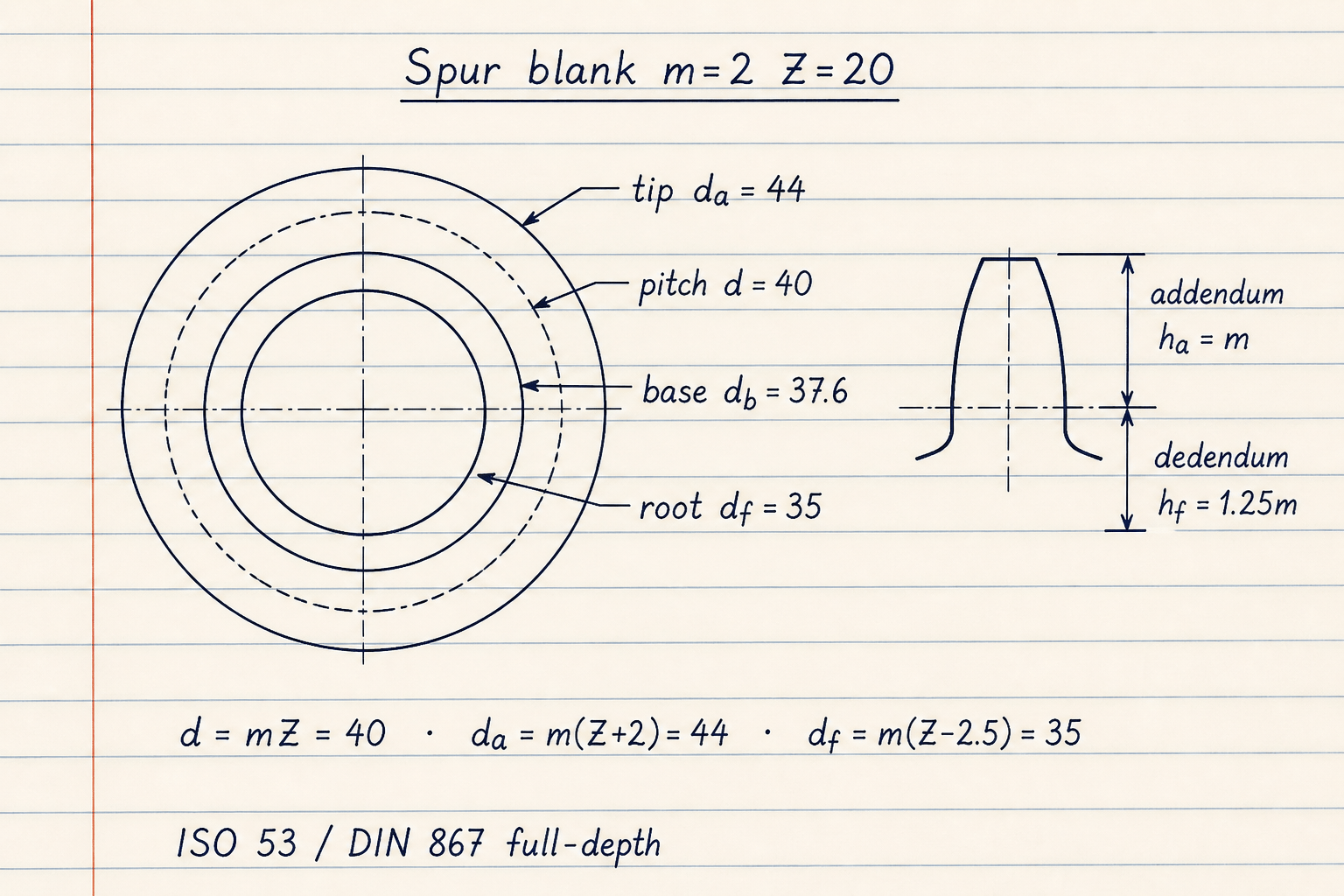
Tip da = m(Z+2) = 44 mm, root df = m(Z−2.5) = 35 mm, base db = d·cos20° ≈ 37.59 mm.
These are nominal zero-backlash full-depth proportions — not a finished drawing with tip relief.
Centre distance from pitch diameters, not outside diameters
Standard external mesh spacing is half the sum of pitch diameters: a = m(Z1+Z2)/2.
Default mate 40T on m2 gives a = 60 mm and i = 2. Contact ratio on this pad uses tip and base radii on the line of action; values near or below 1.2 need a geometry review before you freeze the housing.
Default pair vs a single blank:
| Case | Inputs | Key result |
|---|---|---|
| Pair mode | 20T + 40T · m2 | a = 60 mm · i = 2 |
| Single blank | Mating teeth = 0 | Diameters only · no a |
| DP twin | DP 12.7 · same teeth | Same millimetre blank |
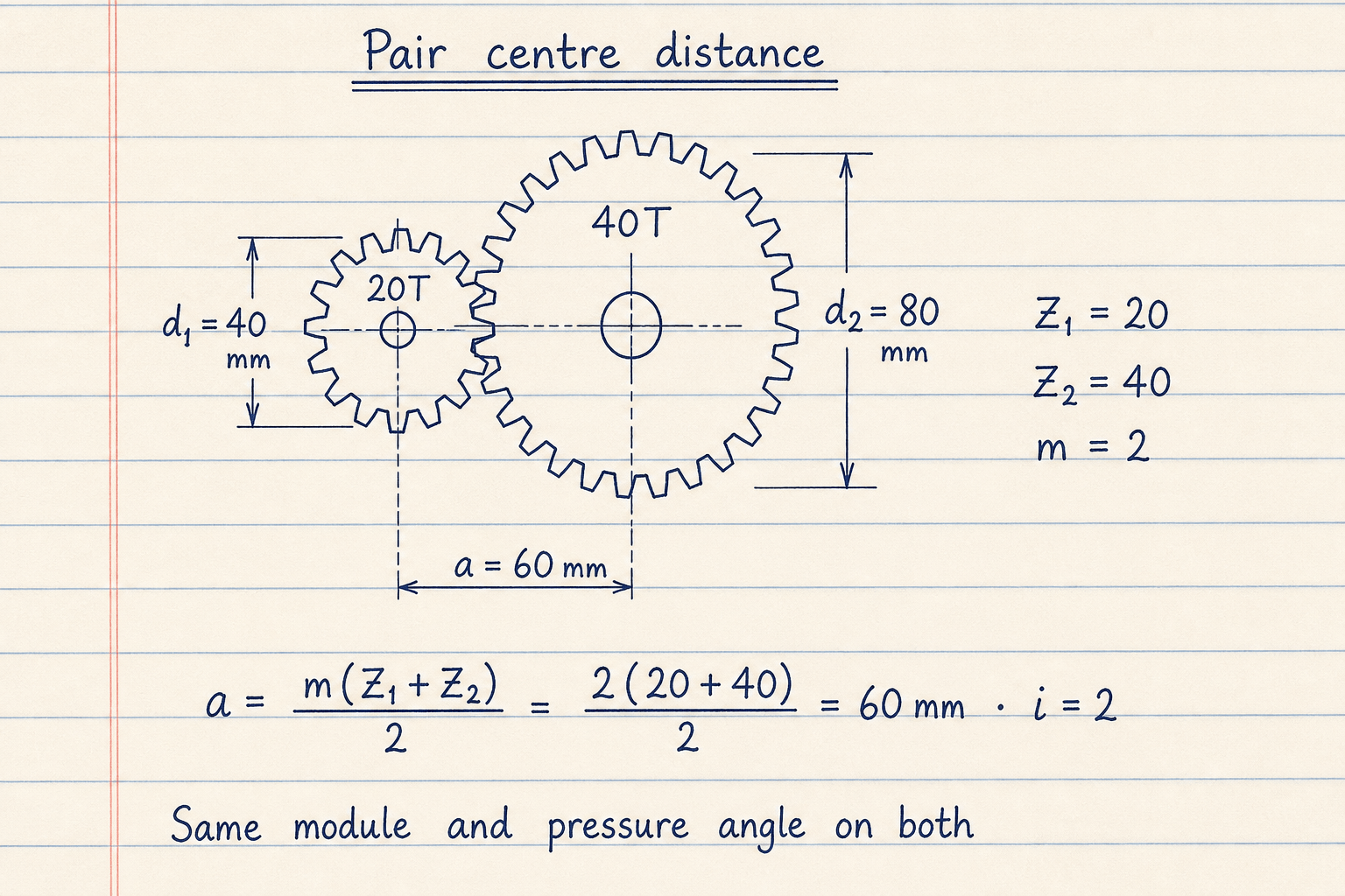
Pitch circles touch at the mesh; outside diameters do not set shaft spacing.
Keep module and pressure angle identical on both members.
Undercut limit depends on pressure angle
Below about 17–18 teeth at 20°, a standard rack generates undercut and weakens the root. Theory gives Z_min = 2/sin²α. At 25° the floor drops near 12 teeth; at 14.5° it rises near 32. This pad warns when your tooth count is under that limit.
Profile shift (addendum modification) can rescue low tooth counts. That correction is out of scope here — treat the warning as a stop sign, then move to a shifted design or a higher pressure angle.
Lewis bending is a screen, not AGMA 2001
Geometry and load rating are separate steps. This pad’s Strength mode uses σ = Ft/(Cv·b·m·Y) with Barth Cv = 3/(3+v) for ordinary cut gears and a tabulated Lewis Y for 20° full-depth teeth. Force triangle mode returns Ft and Fr without FoS.
Example path: m4, 24T, b = 40 mm, 5 kW at 1000 rpm, allowable 140 MPa → Ft ≈ 995 N, σ ≈ 55 MPa, FoS ≈ 2.54 (Pass at ≥ 1.5). Full pitting / AGMA 2001-D04 dynamic factors are not computed here.
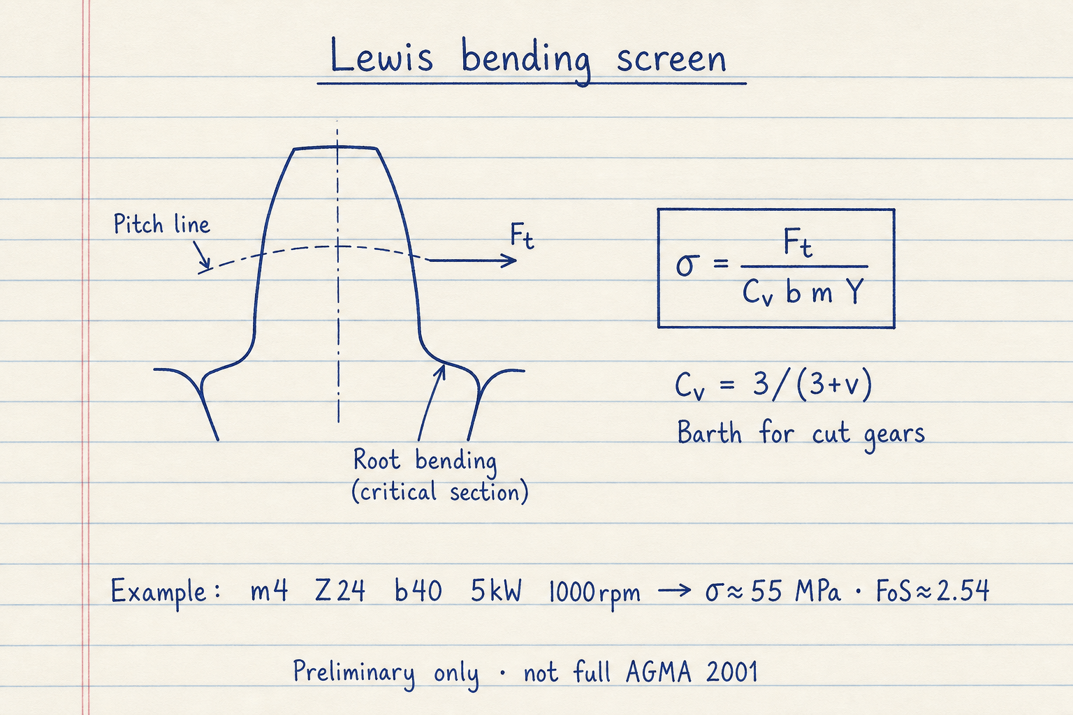
Ft from torque at the pitch radius; Fr = Ft·tanα separates the shafts. Spur mesh has no axial thrust.
Use FoS as a preliminary go/no-go before a catalog rating or AGMA worksheet.
What this pad does not generate
DXF/SVG tooth profiles and measurement-over-pins require dedicated CAD or inspection tools. Use this pad for blank sizing, pair layout, undercut warning, and Lewis screening — then hand off to CAD, inspection, or a signed rating.
Worked example
Default Blank / Pair: m = 2 mm, Z = 20, α = 20°, mating Z = 40. Reproduce on CALCULATE.
- Leave Input mode on Blank geometry, Module, 20° pressure angle.
- Confirm teeth 20, module 2. CALCULATE for d = 40 mm, da = 44 mm, df = 35 mm.
- Switch to Pair / centre distance with mating teeth 40 → a = 60 mm, i = 2, εα ≈ 1.635.
- Optional: Strength mode m4 · 24T · b40 · 5 kW · 1000 rpm · 140 MPa → FoS ≈ 2.54 Pass.
- Force triangle on the same load returns Ft ≈ 995 N and Fr ≈ 362 N without FoS.
Result: Default: d 40 mm, a 60 mm, i 2:1. Strength example: FoS ≈ 2.54 on the m4/24T example.
When to use
- Sizing a spur blank OD/ID before turning
- Setting shaft centre distance for a two-gear mesh
- Converting module ↔ diametral pitch on a replacement gear
- Checking undercut risk at low tooth counts
- First-pass Lewis bending FoS or Ft/Fr forces before catalog selection
Limitations
- External full-depth spur only. No helical, bevel, worm, or internal gears.
- No profile shift, tip relief, or backlash design.
- No DXF/SVG generation or measurement-over-pins.
- Lewis + Barth Cv is a preliminary bending screen, not AGMA 2001 pitting/bending rating.
- Lewis Y uses the common 20° full-depth table for all pressure angles — treat 14.5° / 25° strength as approximate.
- Contact ratio assumes standard addenda; shifted gears need a dedicated tool.
- Results diameters are reported in millimetres even when you enter diametral pitch (m = 25.4/DP).
- Not a substitute for a signed gearbox selection on safety-critical drives.
FAQ
- How do I calculate spur gear pitch diameter?
- d = m·Z in the module system, or D = N/DP in diametral pitch. Defaults: 2×20 = 40 mm.
- What is the outside diameter formula?
- For standard full-depth teeth, da = m(Z+2). Root is df = m(Z−2.5).
- How is centre distance calculated?
- For two external gears with no profile shift, a = m(Z1+Z2)/2. Use Pair / centre distance mode with mating teeth set.
- Module vs diametral pitch?
- m = 25.4/DP. A 2 mm module is about 12.7 DP. Use one system for the whole mesh.
- What tooth count avoids undercut?
- About 18 teeth at 20°, about 12 at 25°, about 32 at 14.5°. The pad warns when you are under Z_min = 2/sin²α.
- Is Lewis the same as AGMA strength?
- No. Lewis with Barth Cv is a quick bending screen. AGMA 2001/2101 adds dynamic, load-distribution, and pitting factors this pad does not compute.
- Does Lewis Y change with pressure angle?
- In a full design yes. This pad uses the common 20° full-depth Y table for every pressure angle and shows a note when Strength mode is not 20°. Use a pressure-angle-specific Y for final work.
Gear Ratio Calculator
Gear ratio, output RPM, and torque for spur pairs, compound trains, direct ratio, speed solve, or idler trains.
Open calculatorHelical Gear Design Calculator
ISO-style helical blank, pair a/εγ, lead, contact ratios, Lewis bending, and Ft/Fa/Fr force triangle — six modes with 2D sketches.
Open calculatorGear Train Calculator
Multi-stage compound gear train (1–4 stages), simple+idler path, or target-RPM reverse ratio with tooth-pair search.
Open calculator