You need the theoretical elastic stress concentration factor Kt at a hole or fillet before you size a plate, shaft shoulder, or elliptical opening. This pad returns Peterson / Pilkey curve-fit Kt, optional local peak stress σmax = Kt·σnom, and optional fatigue Kf when you enter notch sensitivity q.
Defaults open on Metric Geometry mode: central hole in a plate, W = 50 mm, d = 10 mm, σnom = 100 MPa, q = 0.8. CALCULATE returns Kt ≈ 2.506, σmax ≈ 250.6 MPa, Kf ≈ 2.205. Switch to flat-bar or stepped-shaft fillets (tension, bending, torsion), Inglis ellipse, or solve Kt from σmax/σnom. Math stays in your browser.
It sits under Mechanical Calculators next to the fatigue life calculator and von Mises calculator. Pull Kt here, then finish the fatigue screen with Kf on the fatigue pad.
Formula
- Definition: Kt = σmax / σnom (elastic geometry factor).
- Central hole in finite-width plate (Howland): Kt = 3 − 3.14x + 3.667x² − 1.527x³ with x = d/W (best for x ≲ 0.65).
- Shoulder fillets (flat bar or shaft): Kt = C1 + C2·(2h/D) + C3·(2h/D)² + C4·(2h/D)³ where h = (D−d)/2 and Ci are Pilkey polynomials in √(h/r) and h/r (tension, bending, torsion charts differ).
- Elliptical hole in infinite plate (Inglis): Kt = 1 + 2√(a/ρ).
- Fatigue: Kf = 1 + q(Kt − 1) when 0 ≤ q ≤ 1 is entered. Leave q blank to skip Kf.
Reproduce the default Metric plate-hole path on CALCULATE:
| Quantity | Value on this pad |
|---|---|
| W / d / σnom / q | 50 / 10 mm · 100 MPa · 0.8 |
| x = d/W | 0.20 |
| Kt (Howland) | ≈ 2.506 |
| σmax = Kt·σnom | ≈ 250.6 MPa |
| Kf = 1 + q(Kt−1) | ≈ 2.205 |
| Fit band | In range (x ≤ 0.65 preferred) |
How it works
Calculates theoretical elastic stress concentration factor Kt from Peterson / Pilkey curve fits for a plate hole, flat-bar and stepped-shaft fillets (tension, bending, torsion), and an Inglis elliptical hole. Optional nominal stress gives σmax = Kt·σnom; optional notch sensitivity q gives fatigue Kf. Metric or Imperial.
Pick Metric (mm, MPa) or Imperial (in, ksi). Choose solve mode: Geometry → Kt, σmax/σnom → Kt, or Kt × σnom → σmax. In geometry mode pick the feature, enter dimensions and optional σnom and q. CALCULATE locks Results and the sketch. Editing a field clears Results. RESET restores defaults for the active unit system (Metric or Imperial).
Howland plate hole: from infinite Kt=3 to finite width
A hole in a plate is the familiar starting case because the infinite-plate limit is well known: Kt → 3 as d/W → 0. This pad uses the Howland cubic so finite width lowers Kt.
Example: W = 50 mm, d = 10 mm → Kt ≈ 2.506. Tiny hole W = 1000 mm, d = 1 mm → Kt ≈ 3.00. Past x ≈ 0.65 the fit is outside the preferred chart band; the pad flags that in Results.
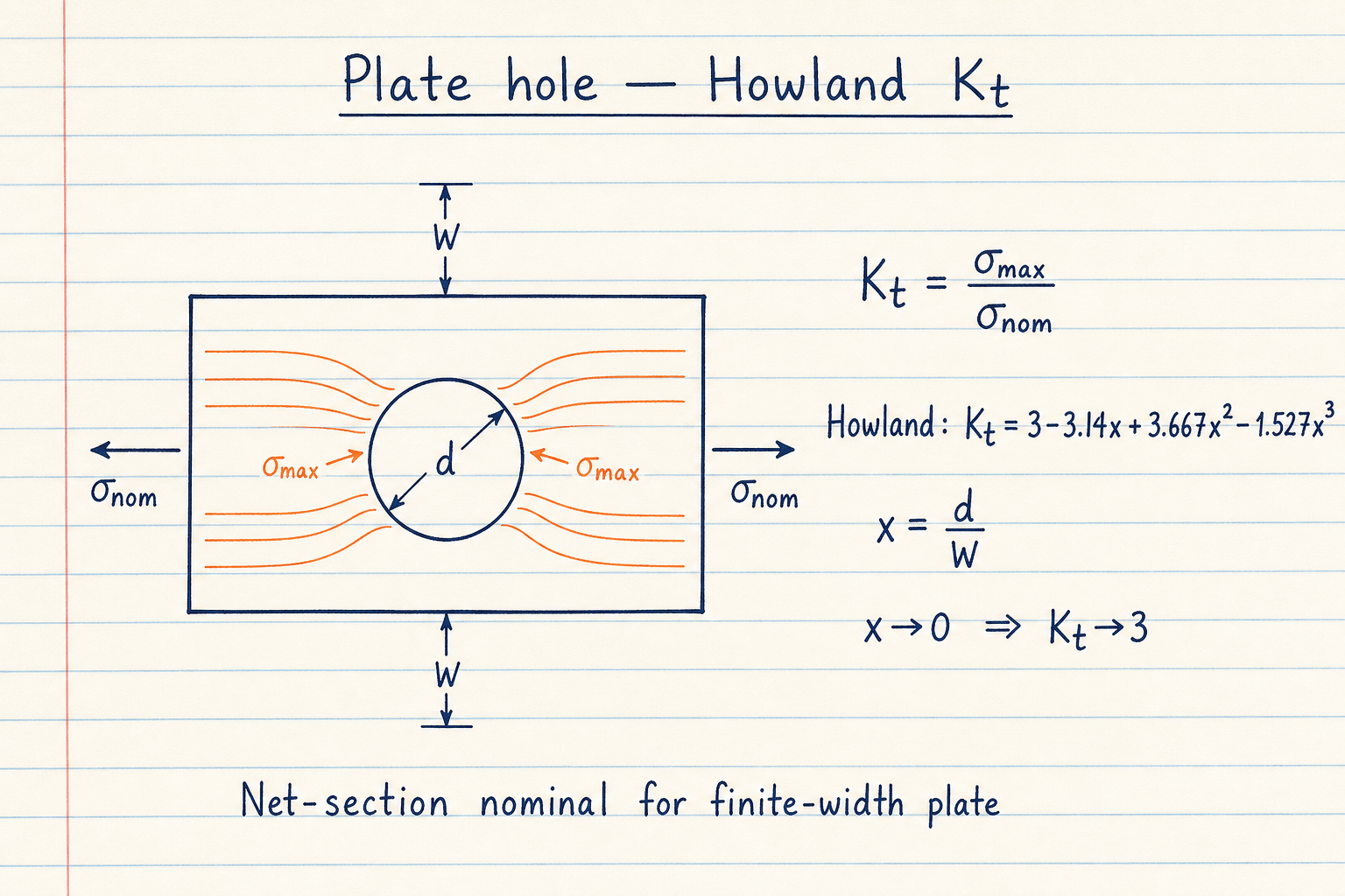
σnom on this pad is the net-section style nominal used with the published Howland fit.
For gross-section FEA stress you may need a different reference; match the chart definition before comparing.
Peterson / Pilkey fillets on bars and shafts
Stepped shafts and shouldered bars dominate machine design. Peterson charts are the reference. This pad ships Pilkey polynomial fits for flat-bar tension and bending plus shaft tension, bending, and torsion.
Example: shaft bending D = 100 mm, d = 80 mm, r = 10 mm → Kt ≈ 1.61. Check h/r against the published band; outside it Results marks the fit out of range even though a number still appears.
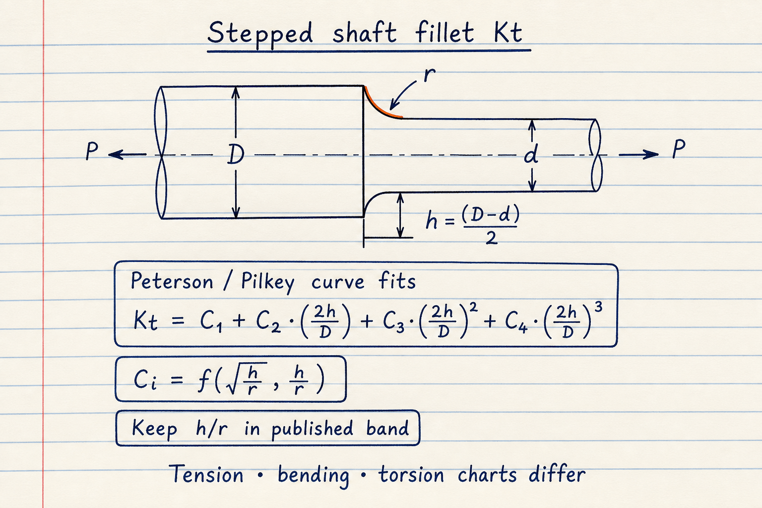
Tension, bending, and torsion use different Ci tables for the same D, d, r.
Blend between low and high h/r coefficient sets near h/r ≈ 2 so the curve stays smooth.
Kt is not Kf: notch sensitivity q
Theoretical Kt multiplies elastic peak stress. Fatigue uses Kf = 1 + q(Kt − 1). The geometry factor is separate from life; finish with q on the fatigue life calculator.
On the defaults, q = 0.8 turns Kt ≈ 2.506 into Kf ≈ 2.205. Leave q blank to skip Kf. Inglis ellipse example: a = 4 mm, ρ = 1 mm → Kt = 5.
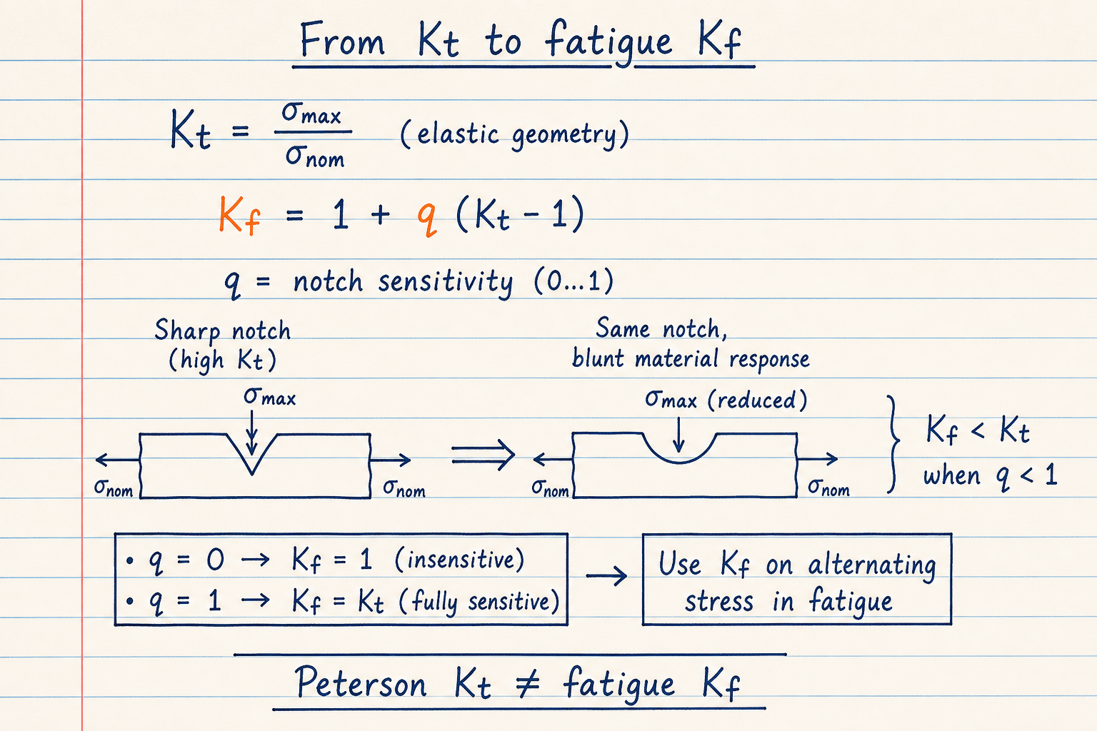
q = 0 means fully notch-insensitive (Kf = 1). q = 1 means Kf = Kt.
Plasticity and Neuber corrections are out of scope on this elastic pad.
Worked example
Default Metric plate hole: W = 50 mm, d = 10 mm, σnom = 100 MPa, q = 0.8.
- Leave Geometry → Kt and Plate · central hole. CALCULATE.
- x = d/W = 0.2 → Howland Kt ≈ 2.506.
- σmax ≈ 250.6 MPa. With q = 0.8, Kf ≈ 2.205.
- Shaft bending example: D = 100, d = 80, r = 10 mm → Kt ≈ 1.61.
- Stress-ratio mode: σmax = 250 MPa, σnom = 100 MPa → Kt = 2.5.
Result: Default: Kt ≈ 2.506, σmax ≈ 250.6 MPa, Kf ≈ 2.205, fit in preferred band.
When to use
- First-pass Kt for a plate hole or shaft shoulder fillet
- Estimating local peak stress from a known nominal stress
- Backing out Kt from measured or FEA peak vs nominal
- Getting Kf from Kt and notch sensitivity before a fatigue check
- Comparing tension vs bending vs torsion charts on the same step
Limitations
- Elastic theoretical Kt only. No Neuber / plastic correction.
- Curve fits approximate Peterson charts; not a substitute for the published figure when you are near a band edge.
- U-notches, keyways, and shoulder undercuts are not covered in this release.
- Nominal stress definition must match the chart (net vs gross).
- Kf needs a realistic q for the material and notch radius; blank q skips Kf.
- Not a code allowable or FEA mesh check.
FAQ
- What is the difference between Kt and Kf?
- Kt is the theoretical elastic concentration from geometry. Kf is the fatigue stress concentration: Kf = 1 + q(Kt − 1). Soft materials or large radii often have q < 1, so Kf < Kt.
- Which nominal stress should I enter?
- Use the same σnom definition as the chart behind the fit. For the plate hole, that is the Howland / net-section style nominal used with d and W. Matching FEA peak to the wrong σnom invents a fake Kt.
- Why does Results say the fit is out of range?
- Pilkey / Howland polynomials are calibrated inside published ratio bands (for example d/W ≲ 0.65 for the hole, and limited h/r for fillets). Outside those bands the number is an extrapolation; treat it as a warning to open the chart or run FEA.
- Can I solve for Kt without geometry?
- Yes. Use σmax / σnom → Kt when you already have peak and nominal stresses, or Kt × σnom → σmax when you already know Kt from a handbook.
- Does this replace Peterson charts or FEA?
- No. It is a transparent screening pad with published curve fits. Critical hardware still needs the chart, a handbook, or a verified mesh.
Fatigue Life Calculator
Marin-corrected endurance limit with Goodman, Soderberg, and Gerber fatigue factors of safety plus Basquin life estimate.
Open calculatorSafety Factor Calculator
Factor of safety from strength ÷ stress. Yield or ultimate basis, material presets, and reverse solve modes.
Open calculatorVon Mises Stress Calculator
Distortion-energy equivalent stress from plane stress, principals, or a 3D tensor, with yield check.
Open calculatorMohr's Circle Calculator
Plane-stress principals, max shear, principal angle, stress transformation, and von Mises from σx, σy, τxy.
Open calculator