You need a first-pass wire rope SWL before a lift, a mass estimate for a cut length, or a reel fill screen. This pad covers those three jobs: empirical MBL ≈ K·d² (or a catalog MBL override), design-factor presets, multi-leg sling angle factors, mass per metre from diameter, and reel capacity with freeboard and dead wraps.
Defaults open on SWL and sling capacity: 12 mm galvanised 6×19, design factor 5:1, single leg. CALCULATE returns MBL = 46.08 kN, SWL ≈ 939 kg, and status Safe when no applied load is entered. Switch to the two-leg 16 mm preset or the mass / reel presets to keep numbers aligned with the worked examples below. Math stays in your browser.
It sits under Mechanical Calculators next to the safety factor calculator and conveyor calculator. Use the safety factor calculator for design-factor checks and the conveyor calculator for line loads.
Formula
- Empirical MBL (kN) ≈ K · d², with K from wire type × construction (optional grade multiplier).
- SWL = MBL / design factor (typical 5:1 general, 6:1 personnel, 3.5:1 static).
- Sling capacity = SWL × angle factor (single = 1; two-leg = 2·cos θ; four-leg ≈ 4·cos θ·0.866).
- Utilization = applied load / sling capacity × 100%.
- Mass per metre ≈ Cw · d² (kg/m); total mass = mass/m × length.
- Reel length L ≈ (A+D)·A·B·K_d with A = (flange−barrel)/2 − freeboard; screen 3 dead wraps and 80% recommended working.
Reproduce the default SWL path on CALCULATE:
| Quantity | Value |
|---|---|
| Inputs | 12 mm · galv · 6×19 · SF 5 · single leg |
| K | 0.32 kN/mm² |
| MBL | 46.08 kN |
| SWL | ≈ 939 kg |
| Mass/m | ≈ 0.518 kg/m |
How it works
Three modes: (1) SWL and sling capacity from empirical MBL ≈ K·d² (or catalog MBL), design factor presets, and multi-leg angle factors; (2) rope mass from length; (3) reel/drum capacity with freeboard and dead-wrap screens. Approximate only — use manufacturer certificates for release.
Pick Input mode (SWL default) or a Quick preset. The animated sketch switches with the mode: hoist elevation (single / two-leg / four-leg), cut-length mass bar, or reel section with H/D/B/X. Wire type and construction stay visible in every mode (they drive MBL and mass/m). CALCULATE fills Results. Editing a field clears Results. RESET restores 12 mm galv 6×19 · SF 5 · single leg.
SWL from diameter is the everyday path
Wire rope SWL calculators start from MBL ≈ K·d² (or a grade form), then SWL = MBL / design factor. This pad keeps that path, adds design-factor presets (5 / 6 / 3.5 / custom), optional EIPS/EEIPS grade multipliers, and a catalog MBL override when you already have a certificate.
Defaults match the legacy example: galvanised 6×19, K = 0.32, 12 mm → MBL = 46.08 kN → SWL ≈ 939 kg at 5:1 on a single leg. Two-leg and four-leg modes apply cos(θ) from vertical; angles under 30° raise a caution.
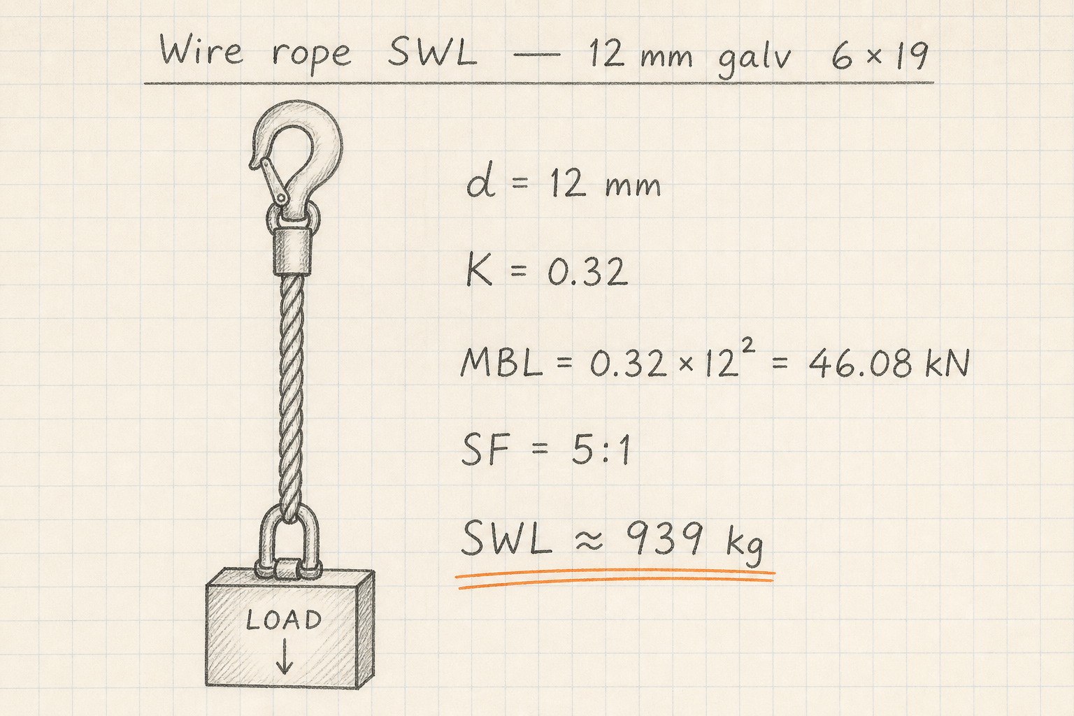
MBL = 0.32 × 12² = 46.08 kN.
SWL = 46.08 × 1000 / 9.81 / 5 ≈ 939 kg (single vertical leg).
Mass per metre and reel fill
Wire weight tables quote mass from diameter and construction. This pad’s Rope mass mode uses Cw·d² screens (≈ 0.518 kg/m for 12 mm galv 6×19) and multiplies by length.
Reel / drum capacity follows the industrial L ≈ (A+D)·A·B·K form. Enter flange, barrel, traverse, and freeboard; keep wire type and construction set because full-reel mass uses the same Cw·d² screen. Results show full capacity, working length after three dead wraps (ASME B30.7 screen), and 80% recommended working for imperfect winding.
Design-factor reminders:
| Duty | Typical SF |
|---|---|
| General lifting | 5:1 |
| Personnel / critical | 6:1 or higher |
| Static / guy | ≈ 3.5:1 |
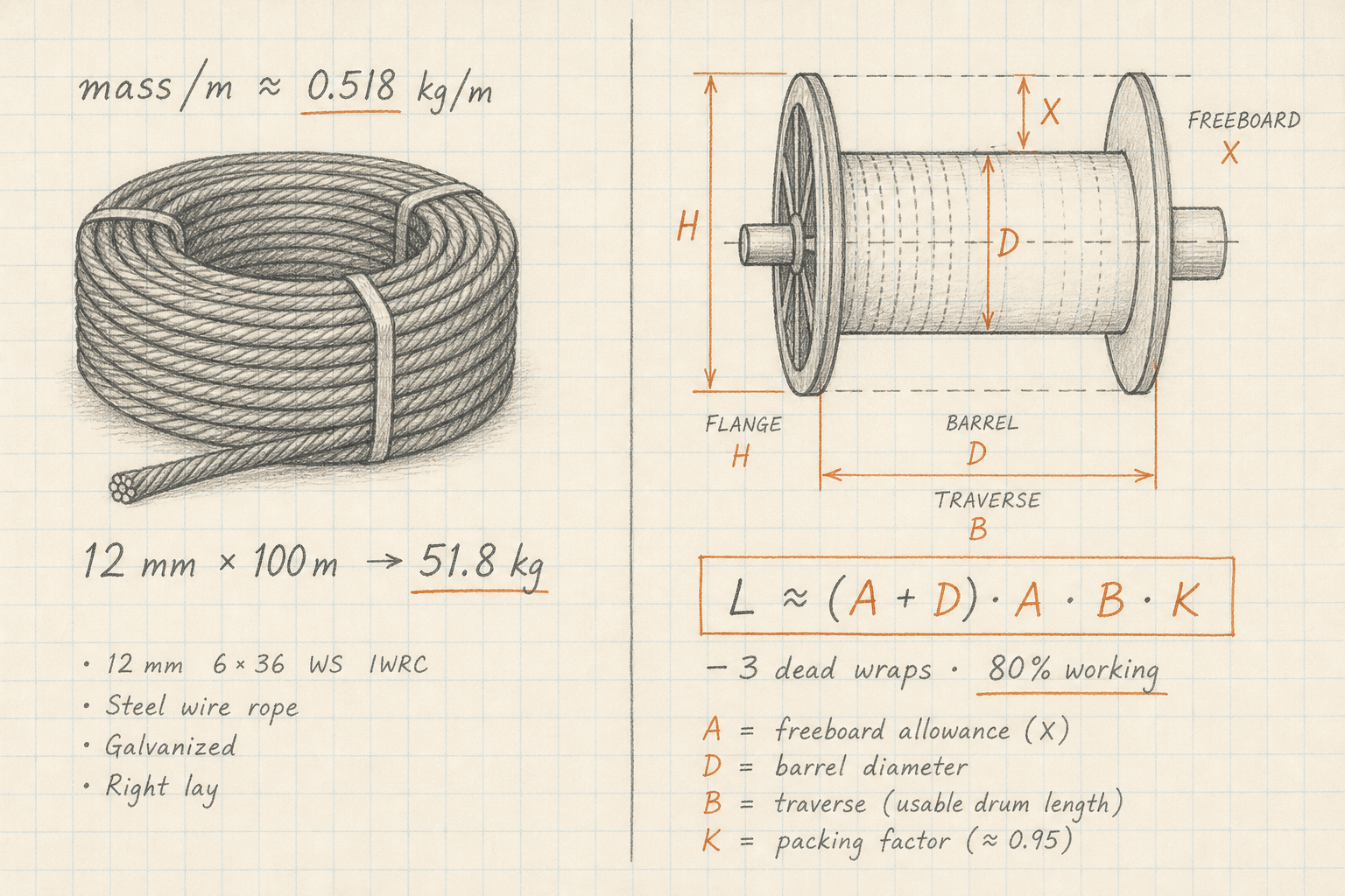
Mass/m ≈ 0.0036 × d² for galv 6×19 (typical screening).
Reel A = (H−D)/2 − X; L from (A+D)·A·B·K; subtract 3 dead wraps for working length.
What this pad is not
Filament-SMYS break-load models (Warrington/Seale packing with quality factors) are specialist products, not this pad. Fibre-rope selection tools target HMPE, aramid, and similar constructions — not steel lifting SWL.
Not termination efficiency maps, dynamic shock factors, or a certified catalog. Paste a catalog MBL when you have one. Always follow local lifting codes and a qualified rigger for release.
Scope boundaries:
| In scope | Out of scope |
|---|---|
| MBL ≈ K·d² / catalog override | Filament SMYS break models |
| Sling angle factors | Fibre rope selection tools |
| Mass/m and reel fill | Termination / splice efficiency maps |
| Utilization vs applied load | Dynamic / shock load factors |
Worked example
Default SWL and sling capacity: 12 mm galvanised 6×19, design factor 5, single leg. Reproduce on CALCULATE.
- Leave Quick preset on 12 mm galv 6×19 · SF5 · single (or enter the same values).
- CALCULATE → MBL = 46.08 kN, SWL ≈ 939 kg, mass/m ≈ 0.518 kg/m.
- Two-leg example: 16 mm, two-leg @ 30°, applied 1500 kg → utilization ≈ 52% (Safe).
- Mass example: 12 mm × 100 m → total ≈ 51.8 kg.
- Reel example: flange 500 / barrel 200 / traverse 300 / freeboard 25, Ø12 → full L ≈ 266 m.
Result: Default SWL ≈ 939 kg. Two-leg 16 mm screen stays under capacity at 1500 kg. Mass ≈ 51.8 kg / 100 m. Reel ≈ 266 m full.
When to use
- First-pass SWL from diameter, construction, and design factor
- Checking multi-leg sling capacity at a known angle
- Estimating rope mass for a cut length or reel fill
- Screening drum capacity with freeboard and dead wraps
- Comparing empirical MBL to a catalog certificate value
Limitations
- Empirical K·d² is a screen, not a manufacturer certificate. Prefer catalog MBL for release.
- Catalog MBL override ignores the empirical K and grade multiplier for strength (still applies design factor and sling geometry).
- No termination, splice, or end-fitting efficiency maps.
- No dynamic / shock load factors or bending fatigue (D/d) life.
- Not filament-SMYS or fibre-rope selection.
- Reel formula assumes uniform winding; non-uniform spooling reduces capacity.
- Always follow local lifting regulations and qualified rigger sign-off.
FAQ
- What design factor should I use?
- General lifting often uses 5:1 on breaking strength. Personnel or critical lifts commonly use 6:1 or higher. Static guy screens sometimes use about 3.5:1. Your code and employer rules control the choice.
- Why does sling angle matter?
- Legs at an angle from vertical share load through cosine components. Shallower angles raise tension in each leg and cut the hitch capacity. Many shops avoid going under 30° from vertical.
- SWL or WLL?
- Safe working load (SWL) is the older term; working load limit (WLL) is the modern label for the same idea: MBL divided by the design factor. This pad labels the result SWL because that is still the common search phrase.
- When should I use catalog MBL?
- Whenever you have a manufacturer certificate or catalog row for the exact rope. Enter that MBL in kN and the pad skips the empirical K·d² screen for strength, still applying your design factor and sling geometry.
- What are dead wraps on a reel?
- The first wraps that stay on the drum to anchor the rope by friction. ASME B30.7-style practice often keeps at least three. This pad subtracts three barrel circumferences from full capacity for a working-length screen.
Conveyor Power and Tension Calculator
CEMA-simplified bulk Te, motor power, and T1/T2, plus package force/torque from drum diameter.
Open calculatorSafety Factor Calculator
Factor of safety from strength ÷ stress. Yield or ultimate basis, material presets, and reverse solve modes.
Open calculatorPress Fit and Shrink Fit Calculator
Lamé contact pressure, hub/shaft stress, torque and press force, yield safety factors, and shrink ΔT for interference fits.
Open calculatorShaft Design Calculator
Minimum shaft diameter from torsion, bending, Guest/Rankine combined, ASME Km/Kt, or twist limit. Solid or hollow.
Open calculator