You need a first-pass clamping force for a woodworking bar clamp, a C-clamp, a vise-grip, a hose clamp, or a Destaco-style toggle / pneumatic fixture clamp — and a quick check against rated holding capacity. This pad picks a category and subtype, applies the matching mechanical-advantage model, and returns Fin, MA, Fclamp, safety factor (Rated ÷ Fclamp), and unused capacity margin.
Defaults open on Imperial with Fast-Action → Toggle Clamp (Excel / Destaco linkage): 100 lbf input, L1 = 2 in, L2 = 1 in, θ = 15° from dead-center, η = 0.85, rated 1500 lbf. CALCULATE returns MA ≈ 7.46, Fclamp ≈ 634 lbf (≈ 2822 N), SF ≈ 2.36. Each subtype draws a distinct 2D sketch in Results (toggle/pneumatic also show Fclamp vs θ). Switch Metric for N / mm / bar, or change category for screw, lever, band, or pneumatic engines.
It sits under Fixture & Tooling Calculators next to the locating pin calculator and tolerance stack-up calculator. Screening only — confirm seals, thread form, and certified ratings on the OEM sheet before release.
Formula
- Toggle / pneumatic link: MA = (L1 / L2) × (1 / tan θ) · θ from dead-center
- Screw / band: MA = 2π × R_handle (or R_drive) / pitch
- Lever / locking: MA = L1 / L2 · Direct / spring: MA = preset (often 1)
- Pneumatic Fin = P × π/4 × D² · else Fin = actuating force
- Fclamp = Fin × MA × η · SF = Rated / Fclamp · Margin = (Rated − Fclamp) / Rated
Reproduce the Excel toggle default on CALCULATE (Imperial):
| Quantity | Value |
|---|---|
| Inputs | Toggle · Fin 100 lbf · L1 2 in · L2 1 in · θ 15° · η 0.85 · rated 1500 lbf |
| MA | (2/1) × (1/tan 15°) ≈ 7.464 |
| Fclamp | 100 × 7.464 × 0.85 ≈ 634.4 lbf (≈ 2822 N) |
| SF / margin | 1500 / 634.4 ≈ 2.36 · ≈ 57.7% unused vs rating |
| Pneumatic check | Ø1.5 in @ 80 psi → Fin ≈ 141.4 lbf → Fclamp ≈ 896.9 lbf |
| C-clamp check | MA = 2π×3.5/0.125 ≈ 175.9 (ideal screw; use η ≈ 0.2 for dry threads) |
How it works
Pick a clamp category and subtype. Toggle/pneumatic use Excel MA = (L1/L2)×(1/tan θ); screw/band use 2πR/pitch; lever uses L1/L2; spring/strap use direct MA. Fclamp = Fin×MA×η. SF = Rated/Fclamp. Metric/Imperial.
Pick Imperial or Metric, then clamp category and subtype. The Results column shows a 2D sketch for that subtype (like the gear-ratio pad’s mode sketches). Inputs follow the engine: toggle/pneumatic show L1/L2/θ plus an Fclamp-vs-θ chart; screw/band show handle radius and pitch; lever shows L1/L2; spring/strap show direct MA. CALCULATE locks Results; editing or changing subtype clears the lock. Rated-capacity chips fill typical catalog screening values.
Toggle MA uses θ from dead-center
Destaco-style hold-down toggles on this pad use the Excel linkage model: MA = (L1 / L2) × (1 / tan θ), with θ measured from the locked dead-center line. Small angles give huge MA; real clamps stop a few degrees short of lock and lose force to friction.
The default Fast-Action → Toggle path (Fin 100 lbf, L1 = 2 in, L2 = 1 in, θ = 15°, η = 0.85) reproduces MA ≈ 7.46 and Fclamp ≈ 634 lbf. Pneumatic subtypes replace Fin with P × π/4 × D², then use the same MA.
Excel toggle default on CALCULATE:
| Quantity | Value |
|---|---|
| Fin · L1 · L2 · θ · η | 100 lbf · 2 in · 1 in · 15° · 0.85 |
| MA | ≈ 7.46 |
| Fclamp | ≈ 634 lbf |
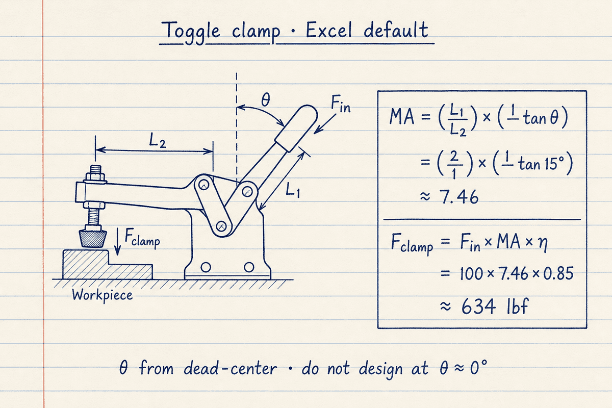
The sketch matches the default Results path: θ is from vertical dead-center, not from the table. At 15° with L1/L2 = 2, MA ≈ 7.46 and Fclamp ≈ 634 lbf at η = 0.85.
Do not design at θ ≈ 0° — tan θ → 0 and the ideal MA diverges. Open the toggle subtype in Results to see the live linkage and Fclamp-vs-θ chart.
Screw clamps multiply by 2πR / pitch
F-clamps, bar clamps, C-clamps, Kant-Twist, and similar subtypes use a square-thread screening model: MA = 2π × handle radius / thread pitch. Ideal MA is large; dry-thread efficiency on this pad defaults near 0.22 so Fclamp stays in a realistic band versus rated capacity.
Metalworking → C-Clamp defaults (R = 3.5 in, pitch = 0.125 in) give ideal MA ≈ 176 before η. Band / hose clamps use the same form with a small worm-drive radius. Confirm lubricated Acme or OEM tables before release — this pad is a first-pass screen.
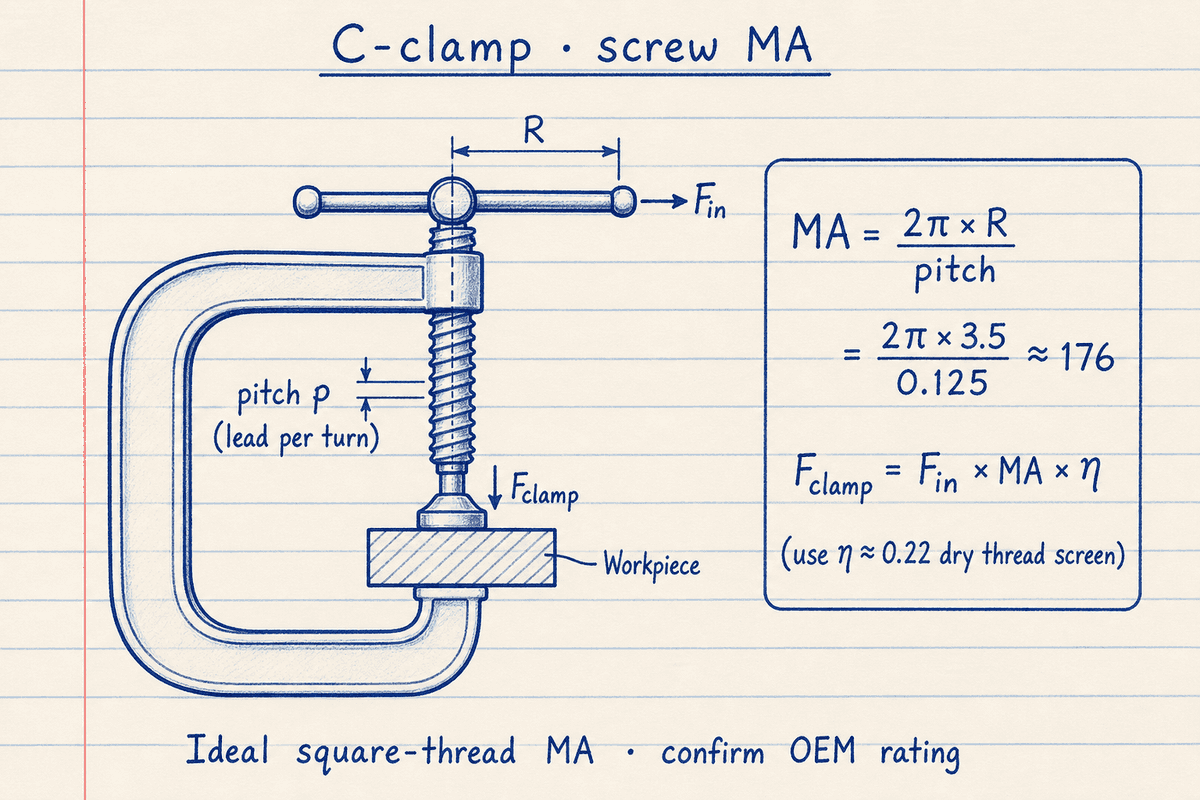
The C-clamp note shows R from the screw axis to the hand force and pitch as lead per turn. MA = 2πR/pitch ≈ 176 for the Metalworking C-Clamp defaults before efficiency.
Pick Metalworking → C-Clamp on the pad; Results draws the C-frame sketch and Fin → MA → Fclamp path instead of a θ chart.
Safety factor is Rated divided by Fclamp
This pad follows the Excel / Destaco screening convention: SF = Rated holding capacity ÷ calculated Fclamp. Margin = (Rated − Fclamp) / Rated. SF above about 2 with unused capacity is common for static fixture hold; SF under 1 means the calculated clamp force exceeds the rating you entered.
Use the Destaco or category typical chips only as fill values. Catalog series ratings vary by spindle position and arm length — always confirm the OEM sheet for the exact clamp.
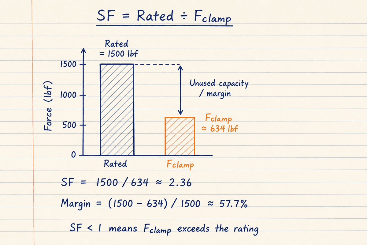
For the Excel toggle default, Rated 1500 lbf over Fclamp ≈ 634 lbf gives SF ≈ 2.36 and about 58% unused capacity versus the rating.
If SF drops below 1, reduce Fin, open θ, lower air pressure, or choose a higher-rated clamp subtype before you treat the hold as safe.
Five categories, six engines
Woodworking and most metalworking screw clamps share the screw engine. Locking pliers, trigger, and cam clamps use lever MA = L1/L2. Spring and magnetic holds use a direct MA (often 1). Hose and cable bands use the band form of 2πR/pitch. Production / fixture adds Destaco-style toggle, latch, straight-line, and pneumatic cylinder / swing / power clamps.
After you lock Fclamp and SF, continue with pin–bushing fit or a 1D tolerance stack-up when the fixture gap budget matters more than clamp force (linked from the overview above).
Worked example
Excel default toggle: 100 lbf input, L1=2 in, L2=1 in, θ=15°, η=0.85, rated 1500 lbf. Reproduce on CALCULATE.
- Leave Imperial and Fast-Action → Toggle Clamp. Confirm Fin 100 lbf, L1 2 in, L2 1 in, θ 15°, η 0.85, rated 1500 lbf.
- CALCULATE. Results shows the toggle sketch, MA ≈ 7.46, Fclamp ≈ 634 lbf, SF ≈ 2.36.
- Optional: Production → Pneumatic Cylinder (Ø1.5 in @ 80 psi) → Fclamp ≈ 897 lbf. Metalworking → C-Clamp for screw MA ≈ 176 before η.
Result: 634 lbf clamp force with SF 2.36 vs 1500 lbf rated capacity.
When to use
- Sizing toggle, latch, or pneumatic fixture clamps from handle force or shop air
- Estimating F/C/bar/hand-screw clamp force from handle radius and thread pitch
- Checking calculated Fclamp against typical rated holding capacity
- Comparing subtypes in a category before picking a catalog series
Limitations
- Idealised single-toggle or square-thread model — OEM clamps may use cams, multi-bar, or Acme friction tables
- Screw η defaults (~0.22) are dry-thread screens, not lubricated efficiency tests
- Pneumatic Fin ignores seal friction and rod area (push on full bore)
- Rated capacities in the tables are typical screening values, not certified catalog rows
- Results SVGs are teaching silhouettes, not OEM envelope drawings
FAQ
- Why does toggle force rise sharply near 0°?
- tan θ → 0 near dead-center, so MA → ∞. Real clamps stop a few degrees short of lock and have friction limits — do not design at θ ≈ 0°.
- How is safety factor defined here?
- SF = Rated holding capacity ÷ calculated Fclamp (Excel convention). SF ≥ 1.5–2.0 is common for static fixture hold; SF < 1 means Fclamp exceeds the rating.
- Which clamp types are included?
- Woodworking (F, parallel, pipe, hand screw, miter, strap, bar, edge), metalworking (C, locking, Kant-Twist, step, welding ground, magnetic), fast-action (trigger, spring, toggle, cam), fluid/utility (hose, beam, cable), and production/fixture Destaco-style toggle and pneumatic families.
- Where is the clamp sketch?
- In the Results column. It switches with category and subtype. Toggle and pneumatic subtypes also show Fclamp versus θ; screw, lever, band, and direct engines show a Fin → MA → Fclamp path.
Tolerance Stack-Up Calculator
1D loop stack-up with worst-case, RSS, adjusted RSS, Cp/Cpk, and contributor ranking — Metric or Imperial.
Open calculatorLocating Pin Fit Calculator
Pin–hole clearance, transition, or interference from ISO-style deviations, plus Lamé press-force screening.
Open calculatorGauge R&R Calculator
MSA Gauge R&R from Xbar-R summary or EV/AV/PV: %GRR vs tolerance and study variation, NDC, AIAG status.
Open calculator