Tightest / loosest pin–hole · live
- Fit type
- Clearance
- Min clearance
- 0.006 mm
- Max clearance
- 0.035 mm
- Mean clearance
- 0.021 mm
- Pin max / min
- 9.994 / 9.983 mm
- Hole max / min
- 10.018 / 10.000 mm
- Contact pressure
- 0.000 MPa
- Assembly / holding force
- 0.0 N
- Extraction force (est.)
- 0.0 N
Hole min − pin max (tightest)
Hole max − pin min (loosest)
Average of min and max clearance
0 when clearance
Fa = Fh = π·di·L·P·μ (Lamé)
≈ 0.7 × assembly (screening)
Preview updates as you type. Press CALCULATE to lock Results for this set of inputs.
You need the pin–bushing fit class for a fixture locator or dowel — clearance for easy load/unload, transition for location, or interference for a press-in pin — plus a screening assembly force when the stack overlaps. This pad takes nominal diameter, pin and hole deviations (or an ISO H7/g6–H7/p6 preset), engagement length, hub OD, material modulus, and friction, then returns size limits, min/max clearance, fit type, and Lamé contact pressure with assembly/holding force.
Defaults open on Metric with a 10 mm H7/g6-style clearance stack: pin −0.006/−0.017, hole +0.018/0. The live preview (right column, same layout as the GD&T fit calculator) shows pin 9.983–9.994 mm, hole 10.000–10.018 mm, clearance 0.006–0.035 mm (Clearance), zero press force. CALCULATE locks those Results. Switch the ISO preset to H7/n6 (transition) or H7/p6 (press/dowel), or Imperial for inch example. Math stays in your browser.
It sits under Fixture & Tooling Calculators next to the ISO 286 tolerance calculator, GD&T fit calculator, and press fit calculator. This pad screens fixture pins — not full two-material thick-wall press design with yield checks (use the press-fit pad for that).
Formula
- Pin max/min = nominal + pin upper/lower deviations (order-independent).
- Hole max/min = nominal + hole upper/lower deviations.
- Max clearance = hole max − pin min; min clearance = hole min − pin max; mean = (min+max)/2.
- Clearance if min clearance ≥ 0; interference if max clearance ≤ 0; else transition.
- Max interference = max(0, −min clearance); Lamé screen when interference or transition can overlap.
- P = (δ/di) · E · (do² − di²)/(do² + di²) (Lamé thick hub; di ≈ nominal).
- Fa = Fh = π · di · L · P · μ; extraction estimate ≈ 0.7 · Fa.
Reproduce the default Metric clearance path on CALCULATE:
| Quantity | Value |
|---|---|
| Inputs | Ø10 · pin −0.006/−0.017 · hole +0.018/0 · L=20 · hub=30 · steel · μ=0.12 |
| Pin / hole | 9.983–9.994 / 10.000–10.018 mm |
| Clearance | 0.006 … 0.035 mm (mean 0.0205) → Clearance |
| Press force | 0 (no interference) |
| H7/n6 example | Transition · δmax ≈ 0.0086 mm → P ≈ 145 MPa · Fa ≈ 10.9 kN (screen) |
| H7/p6 example | δmax ≈ 0.028 mm → P ≈ 471 MPa · Fa ≈ 35.5 kN (above typical yield — screen only) |
| Lamé example | δ=0.025 · do=100 · L=50 · E=200 · μ=0.15 → P=60 MPa · Fa≈70.7 kN |
How it works
Two-column pad (like GD&T fit): enter nominal diameter with pin/hole deviations or an ISO H7/g6–H7/p6 preset. Live preview shows clearance/transition/interference; CALCULATE locks results. Interference screens Lamé contact pressure and assembly force.
Pick Metric or Imperial (tab switch resets defaults). Left column: ISO fit preset (H7/g6 … H7/p6) or custom hole/pin deviations, then material E, μ, engagement length L, and hub OD. Right column: live tightest/loosest cross-section + preview cards (GD&T fit layout). CALCULATE locks Results; editing clears the lock. RESET restores the active unit system’s clearance defaults.
Clearance, transition, and interference — fit classification
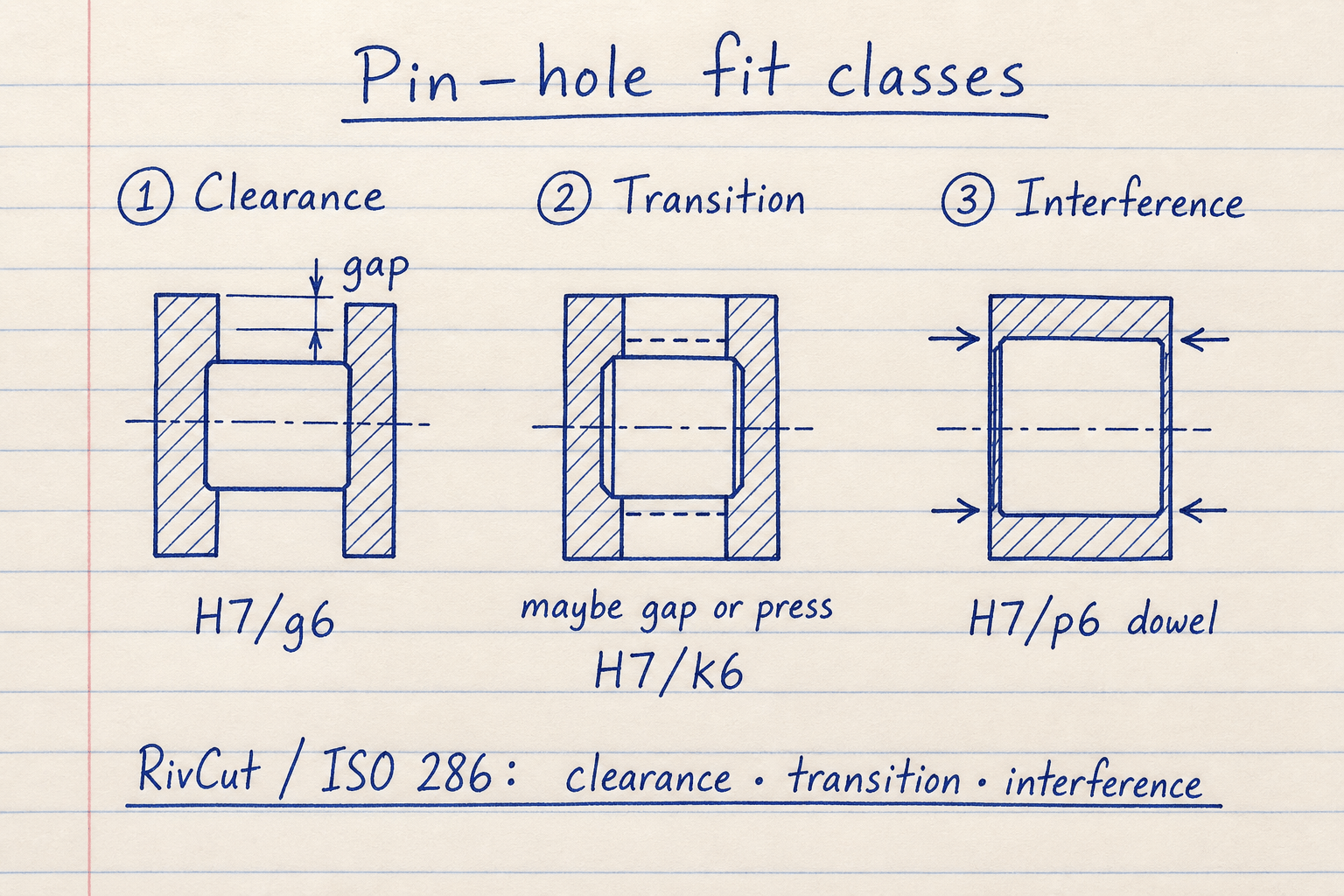
Fit guides classify shaft–hole assemblies the same way shops do: clearance always leaves a gap, interference always overlaps (press or shrink), and transition can land either way inside the tolerance bands. ISO 286 callouts like H7/g6 (sliding), H7/h6 (close sliding), H7/k6–H7/n6 (location), and H7/p6 (light press / dowels) are the usual fixture vocabulary.
Primary locators often use slight clearance for load/unload. Dowels and bushings that must not walk use light interference. Transition fits need process control — a “location” callout can still press or rattle depending on actual sizes.
Common hole-basis fits for pins and locators:
| Fit | Type | Typical use |
|---|---|---|
| H7/g6 | Clearance | Sliding / easy assembly |
| H7/h6 | Clearance | Close sliding, spigots |
| H7/k6 | Transition | Location, slight interference likely |
| H7/n6 | Transition | Tighter location |
| H7/p6 | Interference | Light press, dowel pins |
Default CALCULATE path: clearance 0.006–0.035 mm on Ø10 (H7/g6-style deviations).
Preset H7/p6 on Ø10 always interferes — use force results only as a press screening estimate.
Lamé contact pressure and assembly force
When the stack can interfere, press-fit guides give the thick-hub Lamé screening model used here: contact pressure from diametral interference δ, hole diameter di, hub OD do, and Young’s modulus E; assembly and holding force share Fa = π·di·L·P·μ.
This pad uses maximum interference (tightest MMC pin vs LMC hole) for a conservative press-force screen, assumes a solid pin and the same modulus for pin and hub, and does not check hub yield. For dissimilar materials, Poisson effects, or torque capacity, open the full press-fit calculator.
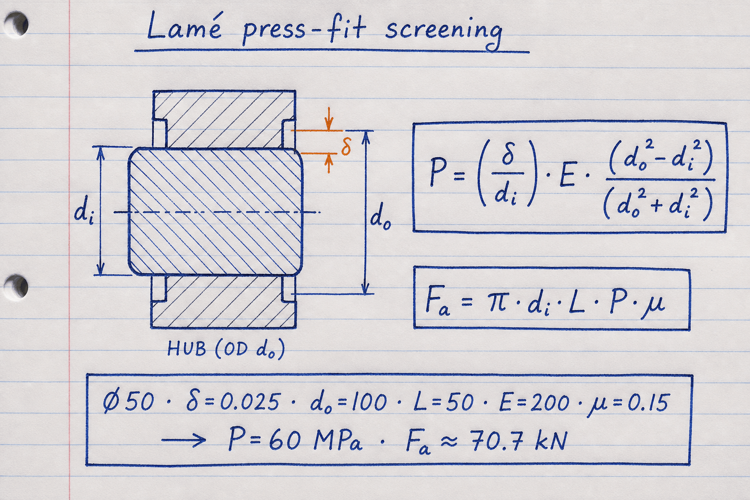
Lamé worked example: Ø50 shaft, δ=0.025 mm, hub OD 100, L=50, E=200 GPa, μ=0.15 → P=60 MPa.
Fa = π·di·L·P·μ evaluates to ≈70.7 kN with diameter di (correct Lamé force). Some informal write-ups halve this — trust the formula with di as diameter.
ISO presets vs custom deviations
Presets call the same ISO 286 engine as the ISO 286 tolerance calculator (hole-basis H7 with g6/h6/k6/n6/p6 shafts). Changing nominal diameter refreshes the micrometer deviations. Custom mode keeps the legacy H7/g6-style shop numbers used for the default verify case, or paste drawing deviations directly.
Always confirm critical fits against your drawing and gage plan — ISO tables and approximated IT grades can differ slightly by source and diameter step.
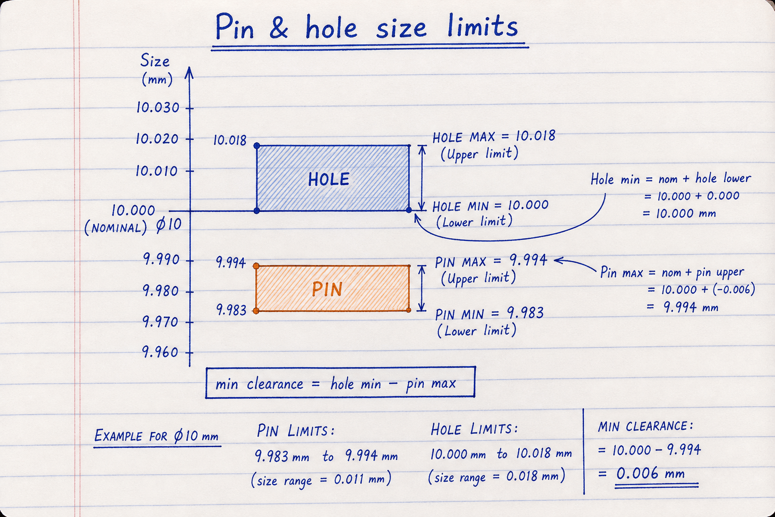
Pin max = nom + pin upper; hole min = nom + hole lower (when hole lower is 0 for H7).
Min clearance = hole min − pin max is the squeeze-or-gap checkpoint for fit class.
Worked example
Default 10 mm Metric clearance stack (H7/g6-style deviations).
- Pin limits: 10 − 0.017 = 9.983 mm to 10 − 0.006 = 9.994 mm
- Hole limits: 10 + 0 = 10.000 mm to 10 + 0.018 = 10.018 mm
- Min clearance = 10.000 − 9.994 = 0.006 mm; max = 10.018 − 9.983 = 0.035 mm
- Both clearances ≥ 0 → Clearance fit; Lamé force = 0
Result: Clearance fit for easy fixture loading; no press force on assembly.
When to use
- Choosing clearance vs press locating pins before fixture detail design
- Screening assembly force on light press / dowel pins (H7/p6-class)
- Converting ISO fit callouts into pin and hole size limits
- Quick Metric/Imperial what-if on engagement length and friction
Limitations
- Lamé screening assumes solid pin, thick hub, same E for both members
- Does not check yield, galling, thermal growth, or surface finish
- ISO preset IT grades follow this site’s ISO 286 engine — confirm drawings
- Extraction force is a 0.7× heuristic, not a measured pull-out test
- Not a substitute for the full two-material press-fit calculator
FAQ
- Clearance vs interference locating pins?
- Primary locators often use slight clearance (H7/g6 or H7/h6) for easy loading. Dowel pins for repeatability often use light interference (H7/p6) or a controlled transition (H7/k6, H7/n6).
- What does fit type mean?
- Clearance: always a gap within tolerance. Interference: always overlap (press/shrink). Transition: actual sizes may clear or interfere.
- Why is press force zero on the default?
- The default deviations are a clearance stack (about H7/g6). Lamé pressure and force only run when interference is possible (interference fit, or transition with max interference > 0).
- How does this differ from the press-fit calculator?
- This pad starts from pin/hole tolerance limits and screens force with a single-modulus Lamé model. The press-fit calculator takes explicit interference and supports shaft/hub materials, Poisson ratio, and yield checks.
- Why can contact pressure look huge on H7/p6?
- Screening uses maximum interference and a stiff single-E Lamé model. On small diameters that can push P well above typical steel yield — treat it as a red-flag estimate, not a validated press design. Check yield on the press-fit calculator or with FEA before tooling.
ISO 286 Tolerance Calculator
ISO 286 hole/shaft limits, deviations, and clearance / transition / interference fit type.
Open calculatorPress Fit and Shrink Fit Calculator
Lamé contact pressure, hub/shaft stress, torque and press force, yield safety factors, and shrink ΔT for interference fits.
Open calculatorTolerance Stack-Up Calculator
1D loop stack-up with worst-case, RSS, adjusted RSS, Cp/Cpk, and contributor ranking — Metric or Imperial.
Open calculatorClamping Force Calculator
Clamping force for woodworking, metalworking, fast-action, hose/beam, and Destaco toggle/pneumatic clamps — with rated-capacity SF.
Open calculatorGD&T Fit Calculator
Shaft-hole MMC/LMC clearance, fit type, and optional virtual-condition go-gauge envelopes.
Open calculator