You need the diametral true position of a hole or pin from CMM or layout deviations — and whether it still passes once MMC or LMC bonus is added. This pad takes X/Y (optional Z) deviations or nominal and measured coordinates, the geometric position tolerance from the feature control frame, material condition (RFS / MMC / LMC), and feature type, then returns true position diameter, bonus, total allowed, percent used, and pass/fail.
Defaults open on Metric · Deviations · 2D · RFS · Hole: dX 0.02 mm, dY −0.01 mm, geometric ∅ 0.1 mm. CALCULATE returns TP ≈ 0.0447 mm, 0 bonus, total allowed 0.1 mm, about 44.7% used, PASS. Switch to MMC with size inputs for the bonus path, or Imperial for the inch example. Math stays in your browser.
It sits under GD&T & Metrology Calculators next to the GD&T fit calculator and ISO 286 tolerance calculator. This pad is a single-feature position check — not projected zones or datum-frame shift.
Formula
- Radial error = √(dX² + dY² [+ dZ²]). True position (diameter) TP = 2 × radial error (ASME Y14.5).
- From coordinates: dX = measured X − nominal X, dY = measured Y − nominal Y.
- RFS: bonus = 0. Total allowed = geometric ∅.
- Hole at MMC: bonus = max(0, actual − MMC). Shaft at MMC: bonus = max(0, MMC − actual).
- Hole at LMC: bonus = max(0, LMC − actual). Shaft at LMC: bonus = max(0, actual − LMC).
- Total allowed = geometric ∅ + bonus. Pass when TP ≤ total allowed. % used = TP / total allowed × 100.
Reproduce the default Metric RFS path on CALCULATE:
| Quantity | Value |
|---|---|
| Inputs | dX 0.02 · dY −0.01 · ∅ 0.1 mm · RFS |
| Radial error | ≈ 0.02236 mm |
| True position | ≈ 0.04472 mm |
| Bonus / total | 0 / 0.1 mm → PASS (~44.7% used) |
| MMC example | dX=dY=0.1 · ∅0.1 · hole MMC 10 · actual 10.2 → TP 0.2828 · bonus 0.2 · PASS |
How it works
TP = 2 × √(dX² + dY²). At MMC or LMC, bonus grows as the feature departs from that size. Total allowed = geometric tolerance + bonus. Pass when TP ≤ total allowed. Pick Metric or Imperial, deviations or nominal/measured coordinates, hole or shaft.
Pick Metric or Imperial (tab switch resets defaults). Choose Entry mode (deviations or nominal/measured X/Y), Axes (2D/3D), Material condition (RFS / MMC / LMC), and Feature type (hole or shaft). MMC/LMC unlocks boundary size and actual size for bonus. CALCULATE fills Results and updates the live zone / bonus sketch (Play/Pause). Editing a field clears Results. RESET restores the active tab’s RFS defaults.
Diametral zone — why TP multiplies by two
Shop true-position tools all use TP = 2 × √(dX² + dY²). The square root is the radial distance from basic true position; the factor of two turns that radius into the diameter of the cylindrical tolerance zone in the feature control frame.
Coordinate (+/−) boxes are rectangular; GD&T position is circular (or cylindrical). That is why the same X and Y deviations can pass position after they would fail a hard ± box — up to about 57% more usable area at the corners of the old square zone.
Quick diametral conversions (same unit as inputs):
| dX | dY | TP diameter |
|---|---|---|
| 0.050 | 0 | 0.100 |
| 0.100 | 0.100 | 0.2828 |
| 0.150 | 0.200 | 0.500 |
| 0.004 | 0.003 | 0.010 |
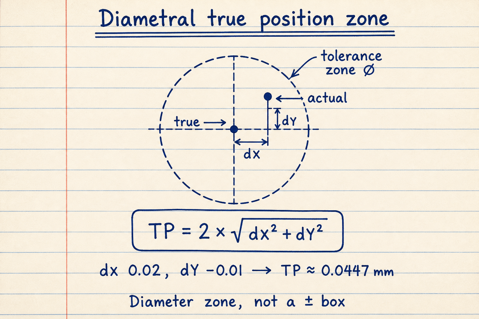
Default CALCULATE path: √(0.02² + 0.01²) × 2 → TP ≈ 0.0447 mm inside a 0.1 mm zone.
Equal offsets at 45° use the most of a circular zone for a given X/Y pair.
MMC and LMC bonus — when size buys position
The classic RFS-fail → MMC-pass story: same 0.004 / 0.003 deviations give TP 0.010 against a 0.008 callout (fail at RFS), but with MMC and a hole opened 0.007 past MMC the total allowed grows to 0.015 and the feature passes.
Bonus is never negative. For a hole at MMC it is actual − MMC; for a shaft at MMC it is MMC − actual. LMC flips the departure direction. Some tools report an MMC adjustment subtracted from effective error — this pad reports the clearer total-allowed form.
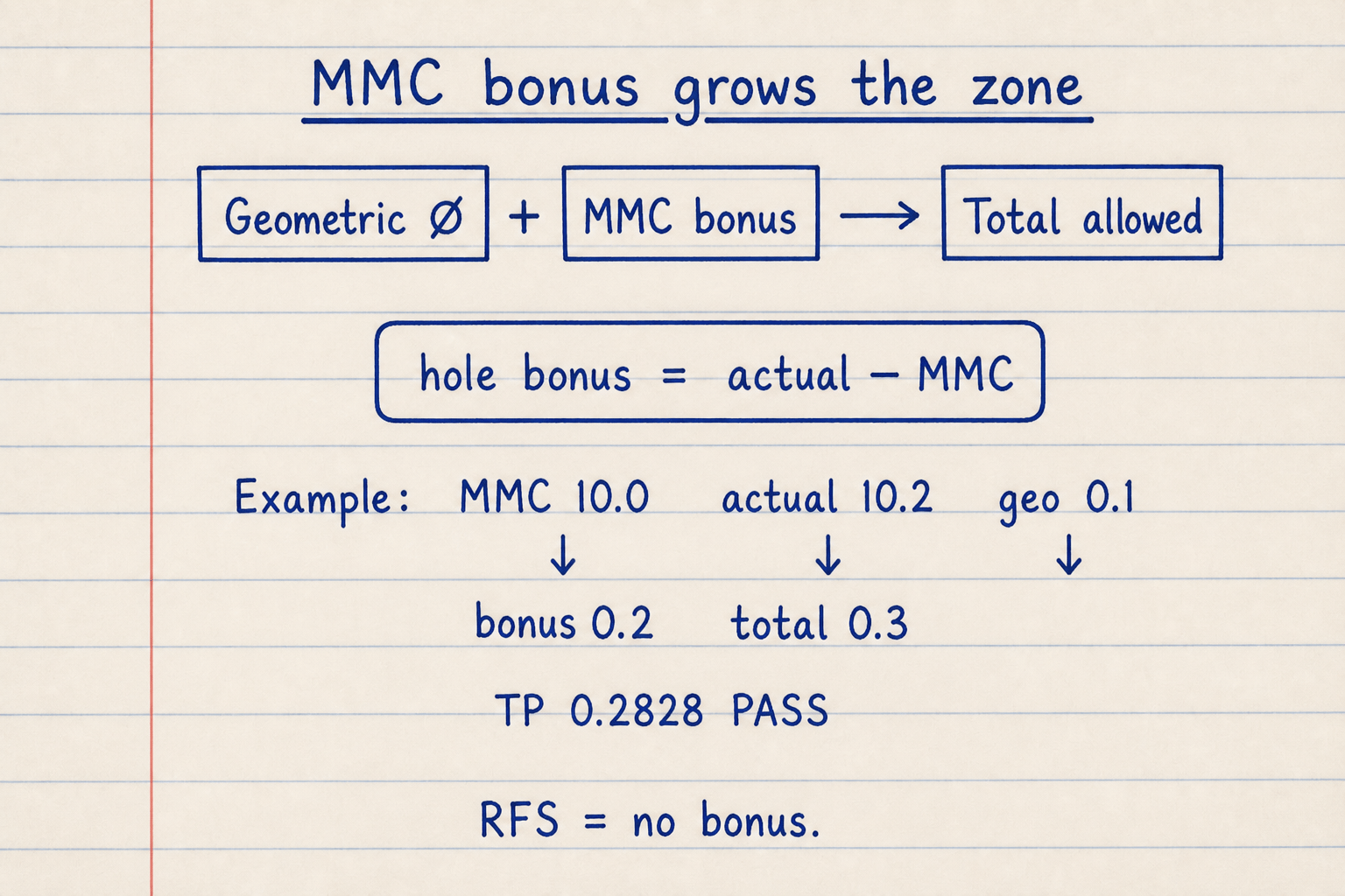
MMC example: dX=dY=0.1, ∅0.1, hole MMC 10, actual 10.2 → bonus 0.2, total 0.3, TP 0.2828 → PASS ~94%.
RFS sets bonus to zero — total allowed equals the listed geometric diameter only.
Deviations vs nominal and measured coordinates
True-position utilities accept either pre-computed offsets or basic dimensions with measured coordinates. This pad’s Entry mode switch covers both shop workflows.
Projected tolerance zones, feature-height interpolation, and full datum-frame modeling stay out of scope — use a CMM package when the callout includes Ⓟ or simultaneous requirements on a pattern.
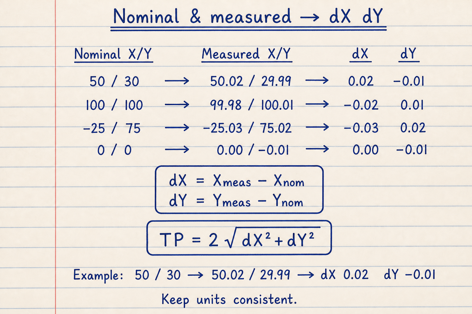
Coordinate mode: dX = measured X − nominal X; dY = measured Y − nominal Y; then the same TP formula.
Keep units consistent — Metric or Imperial tab — across every input.
Worked example
Default Metric · Deviations · 2D · RFS · Hole: dX 0.02 mm, dY −0.01 mm, geometric ∅ 0.1 mm. Reproduce on CALCULATE.
- Leave Metric, Deviations, 2D, RFS. CALCULATE → TP ≈ 0.0447 mm · bonus 0 · total 0.1 · PASS.
- MMC example: MMC, hole, dX=dY=0.1, ∅0.1, MMC size 10, actual 10.2 → TP 0.2828 · bonus 0.2 · PASS.
- Inch example: Imperial, dX 0.004, dY 0.003, ∅0.008 at RFS → TP 0.010 FAIL; switch MMC with MMC 0.620, actual 0.627 → total 0.015 PASS.
- Coordinate example: Nominal & measured, 50 / 30 basic, 50.02 / 29.99 measured → same TP as default deviations.
Result: Default: TP ≈ 0.0447 mm PASS. MMC path: TP 0.2828 vs 0.3 allowed PASS. RFS inch path fails until MMC bonus is applied.
When to use
- CMM or layout true position check from X/Y deviations
- Applying MMC or LMC bonus from measured feature size
- Converting nominal and measured coordinates to diametral TP
- Quick Metric ↔ Imperial position screening
- Reporting % of tolerance used and pass/fail margin
Limitations
- No projected tolerance zone (Ⓟ) or feature-height interpolation.
- No datum reference frame shift or pattern simultaneous requirements.
- Does not validate measured size against drawing size limits (enter size for bonus only).
- 3D mode adds dZ to the radial term; confirm that matches your inspection method.
- Not a full ISO GPS vs ASME comparison tool.
FAQ
- Why multiply by 2?
- ASME Y14.5 position tolerance is a diameter zone. Radial deviation from true position is doubled so it compares directly to the ∅ value in the feature control frame.
- What is bonus tolerance?
- Extra position tolerance earned when a feature departs from MMC or LMC (when that modifier is specified). For a hole at MMC, bonus = actual size − MMC size. Add it to the listed geometric tolerance.
- RFS vs MMC vs LMC?
- RFS (default) gives no size bonus. MMC is most common for assembly — bonus grows as a hole opens or a pin shrinks. LMC is used when wall thickness or minimum material matters; bonus grows toward MMC.
- Does TP equal to the tolerance pass?
- Yes. Pass when measured true position diameter is less than or equal to total allowed (geometric ∅ + bonus).
- 2D vs 3D mode?
- Use 2D for typical hole patterns on a plane. Enable 3D when your report includes a Z contribution to the location error vector.
GD&T Fit Calculator
Shaft-hole MMC/LMC clearance, fit type, and optional virtual-condition go-gauge envelopes.
Open calculatorISO 286 Tolerance Calculator
ISO 286 hole/shaft limits, deviations, and clearance / transition / interference fit type.
Open calculatorGauge R&R Calculator
MSA Gauge R&R from Xbar-R summary or EV/AV/PV: %GRR vs tolerance and study variation, NDC, AIAG status.
Open calculator