You need the standard parallel key size for a shaft and a quick shear / bearing screen before you broach a hub or slot a gear. This pad looks up b, h, and keyseat depths from ANSI B17.1 or ISO 773, then checks key shear and crushing stress under torque with optional service factor Ks.
Defaults open on Metric ISO 773: D = 40 mm, L = 50 mm, T = 200 N·m, τallow = 60 MPa, σallow = 100 MPa, Ks = 1, target FOS = 1.5. CALCULATE returns b × h = 12 × 8 mm, recommended L ≈ 60 mm, τ ≈ 16.7 MPa, σb ≈ 50 MPa, FOS ≈ 3.6 / 2.0, Pass. Switch to ANSI B17.1 in Imperial for inch-series keys. Math stays in your browser.
It sits under Mechanical Calculators next to the shaft design calculator and press fit calculator. Size the shaft first, then pick the standard key row and check L against torque here.
Formula
- Standard row: shaft diameter D selects key width b, height h, shaft depth t1, hub depth t2 (ANSI B17.1 or ISO/R 773 tables on this pad).
- Recommended length Lrec ≈ 1.5 × D (standard guidance; keep L ≤ 1.5D when possible).
- Tangential force F = T / (D/2) = 2T/D.
- Key shear τ = Ks · F / (b · L · N). Bearing σb = Ks · F / ((h/2) · L · N) with N = number of equal keys.
- FOS shear = τallow / τ. FOS bearing = σallow / σb. Pass when both FOS ≥ target.
- Minimum length: Lmin = max(Ks·F/(τallow·b·N), Ks·F/(σallow·(h/2)·N)).
Reproduce the default Metric ISO path on CALCULATE:
| Quantity | Value on this pad |
|---|---|
| D / L / T | 40 / 50 mm · 200 N·m |
| Standard key | 12 × 8 mm (ISO 773 row) |
| F = 2T/D | 10,000 N |
| τ / σb | ≈ 16.7 / 50 MPa |
| FOS (τ / σb) | ≈ 3.6 / 2.0 vs target 1.5 |
| Check | Pass · L within 1.5×D |
How it works
Looks up parallel key width, height, and keyseat depths from ANSI B17.1 or ISO 773 tables, then checks shear and bearing (crushing) stress under transmitted torque. Returns factors of safety, minimum key length, and a Pass/Fail screen vs your target FOS. Metric or Imperial.
Pick Metric or Imperial. Choose ANSI B17.1 or ISO 773 and auto table lookup, or manual b/h. Enter shaft diameter, key length, torque, allowable stresses, optional Ks and key count, and target FOS. CALCULATE locks Results and the sketch. Editing clears Results. RESET restores defaults for the active unit system (Metric keeps ISO; Imperial switches to ANSI).
Standard key size follows shaft diameter, not guesswork
Keyway calculators start from a standard table: pick D, read b, h, and keyseat depths. This pad ships ANSI B17.1 (inch series) and ISO 773 (metric) rows used in Machinery's Handbook charts.
Example: 1 in shaft under ANSI → preferred square 1/4 × 1/4 in key with shaft depth 1/8 in. Metric D = 40 mm under ISO 773 → 12 × 8 mm key. Custom widths cost broach tooling; sticking to the standard row saves shop time.
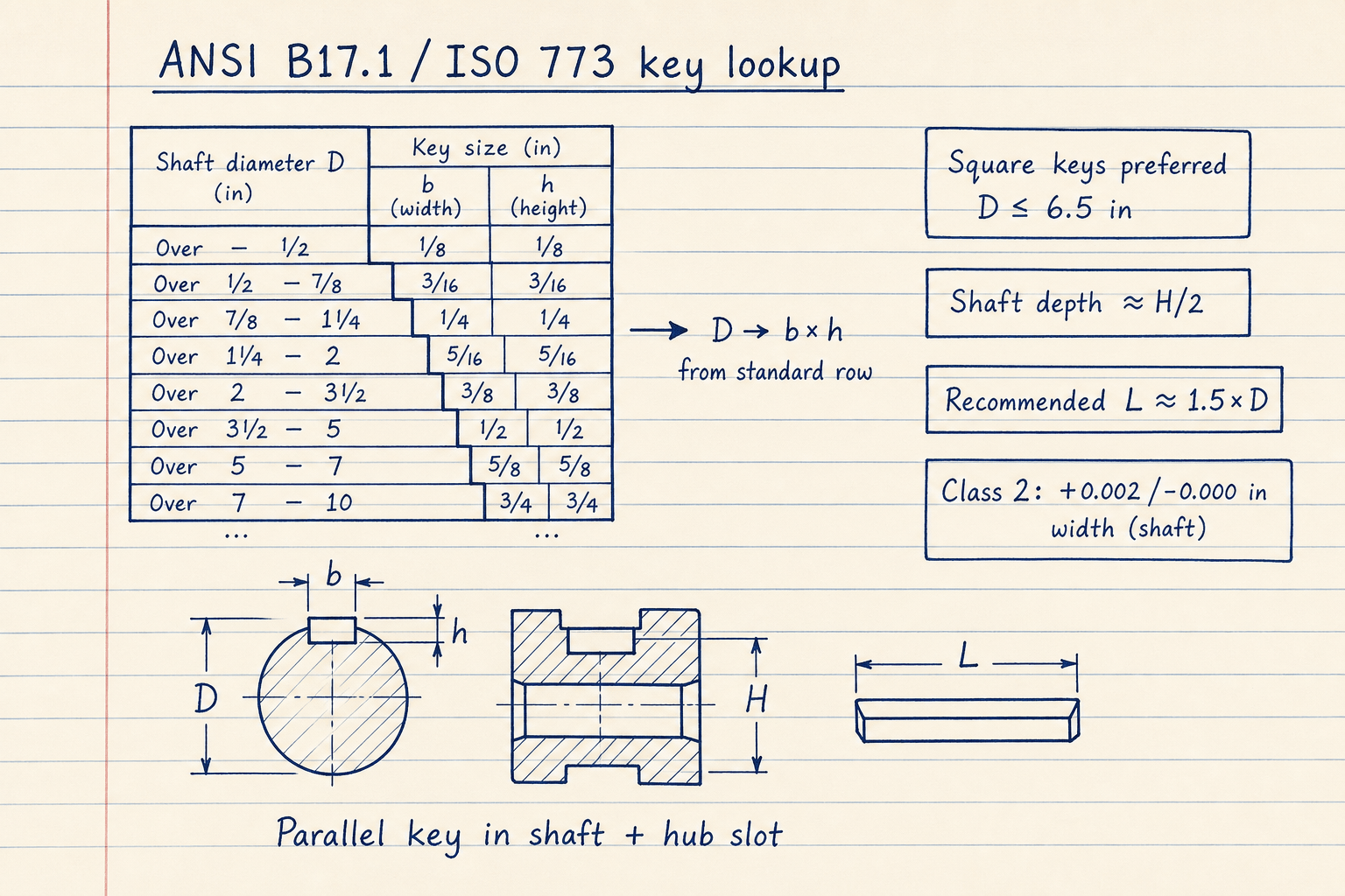
Square keys dominate smaller ANSI shafts; rectangular keys appear on larger diameters.
Class 2 normal fit is the default reference; Class 1 and 3 change width tolerances and intent.
Shear and bearing: two failure modes on the same key
Key design references warn that a key can fail in shear or in bearing (crushing) on the hub side. This pad checks both and reports the governing minimum length.
On the defaults, F = 10 kN, τ ≈ 16.7 MPa, σb ≈ 50 MPa. Bearing often governs minimum length (≈ 25 mm here) even when τ looks comfortable.
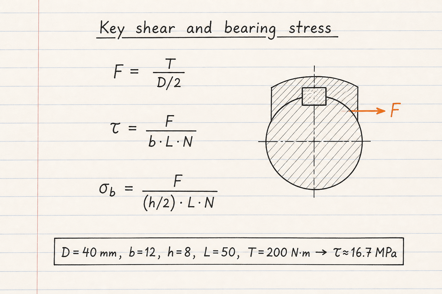
Contact depth uses h/2 for square-key screening (Shigley style).
Multiple keys divide force by N but need 90° spacing and equal load share.
Length limit and service factor Ks
Standard practice recommends L < 1.5D so twist does not overload one end of the key. Application, keyway, fatigue, and wear factors can be folded into Ks for shock or duty margin. This pad exposes a single Ks multiplier (default 1) on stress.
If L > 1.5D the pad still calculates stress but flags length guidance. For a sliding fit hub, use Class 3 notes and expect higher Kd on a full spline worksheet; that detail is out of scope here.
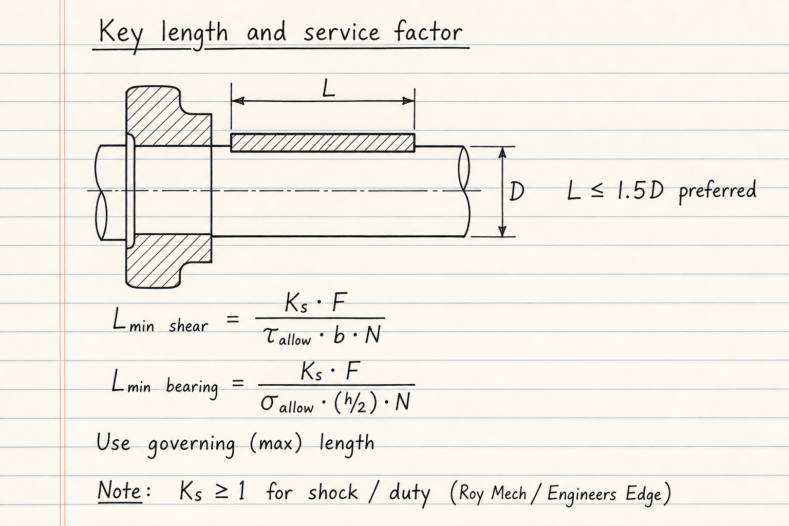
Minimum length uses the larger of shear and bearing requirements.
Key material is often weaker than the shaft so the key acts as a sacrificial element in some designs.
Worked example
Default Metric ISO: D = 40 mm, L = 50 mm, T = 200 N·m, τallow = 60 MPa, σallow = 100 MPa, target FOS = 1.5.
- Leave ISO 773 and Auto from standard. CALCULATE.
- Table row → 12 × 8 mm key, shaft depth 5 mm, hub depth 3.3 mm.
- F = 10,000 N → τ ≈ 16.7 MPa, σb ≈ 50 MPa.
- FOS ≈ 3.6 (shear) and 2.0 (bearing) → Pass vs 1.5.
- Governing Lmin ≈ 25 mm (bearing). Recommended Lrec = 60 mm.
Result: Pass at target 1.5; bearing governs minimum length.
When to use
- Looking up ANSI B17.1 or ISO 773 key size from shaft diameter
- First-pass parallel-key shear and bearing check under torque
- Finding minimum key length for given allowables
- Comparing one key vs two keys on the same torque
- Documenting Class 2 fit tolerance notes before machining
Limitations
- Parallel keys only. No Woodruff, taper, or splines.
- Tables cover common diameter bands; extreme sizes need the full standard PDF.
- No hub/key material automatic allowables; enter τallow and σallow yourself.
- No fatigue notch or keyway Kt on the shaft (see stress concentration pad).
- Sliding-fit Kd and full application-factor tables are not built in; use Ks as a simple margin.
- Not a substitute for a certified drawing or broach shop sign-off.
FAQ
- ANSI B17.1 or ISO 773?
- Use ANSI B17.1 for inch-series machinery keys and ISO 773 (same family as DIN 6885) for metric shafts. The pad auto-selects ISO in Metric and ANSI in Imperial defaults, but you can override.
- Why is hub keyway depth different from shaft depth?
- Standards split key height between shaft and hub with a small clearance so the key seats cleanly. Machinery's Handbook lists both depths; this pad returns both from the table row.
- Which stress usually governs?
- Bearing on the hub side often sets the minimum length because contact area uses h/2. Shear can govern on short, wide keys. The pad reports both FOS and the governing Lmin.
- What is a good key length rule?
- Stay near L ≈ 1.5D unless you have a reason to go longer. Very long keys see uneven load when the shaft twists.
- Does this replace a shaft stress check?
- No. It sizes the key connection. Use the shaft design calculator for diameter under bending and torsion, and remember keyways cut allowable shear on the shaft section.
Shaft Design Calculator
Minimum shaft diameter from torsion, bending, Guest/Rankine combined, ASME Km/Kt, or twist limit. Solid or hollow.
Open calculatorPress Fit and Shrink Fit Calculator
Lamé contact pressure, hub/shaft stress, torque and press force, yield safety factors, and shrink ΔT for interference fits.
Open calculatorBolt Torque Calculator
Tightening torque from diameter, target preload, and lubrication K. Metric ISO or inch UNC, reverse clamp load, and % of proof.
Open calculatorStress Concentration Factor (Kt) Calculator
Peterson / Pilkey Kt for holes, flat-bar and shaft fillets, plus optional σmax and fatigue Kf.
Open calculator