- Flat Pattern Length
- n/amm
- Bend Allowance
- n/amm
- Bend Deduction
- n/amm
- Outside Setback
- n/amm
- Neutral Radius
- n/amm
- Outside Radius
- n/amm
Before you laser a blank or program a brake, you need the developed flat length for each bend. This pad takes thickness, formed bend angle, inside radius, and K-factor, then returns bend allowance, bend deduction, outside setback, neutral and outside radii, and the flat pattern length.
Pick Metric (mm) or Imperial (in), then choose how you measured the flanges: Bend-line flanges add BA to the legs, Outside mold lines subtract BD. Material presets fill a starting K only. CALCULATE runs the same air-bend K-factor formulas used in CAD unfold. Math stays in your browser.
It sits under Sheet Metal Calculators with other form tools. Check cracking risk on the minimum bend radius calculator before you lock a tight inside radius. Punch clearance and tonnage live on the punch and die calculator.
Formula
- Neutral radius Rₙ = Rᵢ + K × T. Outside radius Rₒ = Rᵢ + T.
- Bend allowance BA = (π/180) × θ × (Rᵢ + K × T), with θ the formed bend angle in degrees (90° for a right-angle corner).
- Outside setback OSSB = tan(θ/2) × (Rᵢ + T). Bend deduction BD = 2 × OSSB − BA.
- Bend-line flanges: Flat = Leg A + Leg B + BA. Outside mold lines: Flat = Leg A + Leg B − BD.
Default Metric worked path (Bend-line flanges, Custom K = 0.33):
| Quantity | Value |
|---|---|
| Thickness T / Inside radius Rᵢ | 2 mm / 2 mm |
| Bend angle θ / K-factor | 90° / 0.33 |
| Leg A / Leg B (to bend lines) | 40 mm / 40 mm |
| Neutral radius Rₙ | 2.66 mm |
| Bend allowance BA | 4.18 mm |
| Outside setback OSSB | 4.00 mm |
| Bend deduction BD | 3.82 mm |
| Flat pattern (bend-line mode) | 84.18 mm |
| Flat pattern if same legs as OML | 76.18 mm |
How it works
Pick Metric or Imperial, then Bend-line flanges or Outside mold lines. Enter thickness, bend angle θ (formed bend, 90° for a right-angle corner, max 179°), inside radius, and K-factor (material presets fill a starting K). CALCULATE returns bend allowance, bend deduction, outside setback, flat pattern length, and radii, and runs the 3D forming sketch. Bend-line mode adds BA to the legs. Outside mold-line mode subtracts BD. Editing inputs or switching mode clears Results. RESET restores the 2 mm / 90° / K 0.33 defaults for the active unit tab.
Choose Metric or Imperial. Pick Bend-line flanges or Outside mold lines. Optional material preset fills a typical starting K (mild steel 0.42, aluminum 0.35, stainless 0.45, copper 0.35, brass 0.38). Enter thickness, bend angle θ (1° to 179°), inside radius, K-factor, and both legs. CALCULATE shows BA, BD, OSSB, flat length, Rₙ, and Rₒ, and starts the 3D forming sketch. Editing a field or switching measure mode clears Results. RESET restores the 2 mm / 90° / Rᵢ 2 mm / K 0.33 / 40 mm legs defaults for the active unit tab (measure mode stays as selected).
Bend-line flanges vs outside mold lines
The same BA and BD come out either way. What changes is how you measured Leg A and Leg B on the print.
Bend-line mode expects flange lengths to the tangent where the straight leg meets the bend arc. That is the length that sits flat outside the bend region, so Flat = A + B + BA.
Outside mold-line mode expects finished outside dimensions to the sharp corner where the outside faces would meet if they continued past the bend. Those lengths already include the setbacks, so Flat = A + B − BD. Mix the modes and the blank comes out long or short by about 2 × OSSB.
K-factor and the neutral axis
During forming, the inside of the bend compresses and the outside stretches. Between them sits a neutral axis that keeps its length. K-factor is the distance from the inside surface to that axis, divided by thickness: K = t / T.
Typical starting values fall between about 0.30 and 0.50. Softer aluminum often starts near 0.33 to 0.40. Cold-rolled steel often starts near 0.40 to 0.45. Stainless is often a bit higher. Radius, V-die opening, and air bend vs coining move K, so a press-brake bend table from your shop beats any preset on this page.
If you already measured bend allowance from a test coupon, you can back-solve K = ((BA / θ_rad) − Rᵢ) / T and store that for the next blank of the same setup.
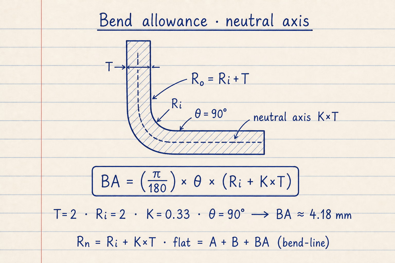
The note shows a 90° L-bend: thickness T, inside radius Ri, outside Ro = Ri + T, and a dashed neutral axis at K × T from the inside.
BA = (π/180) × θ × (Ri + K×T). Default Metric path T=2, Ri=2, K=0.33, θ=90° → BA ≈ 4.18 mm. Flat in bend-line mode is A + B + BA.
Bend deduction and outside setback
Outside setback is the distance from the outside mold-line apex to each bend tangent along the outside face: OSSB = tan(θ/2) × (Rᵢ + T). For a sheet metal bend at 90° with Ri = 2 mm and T = 2 mm, OSSB = 4.00 mm.
Bend deduction is how much shorter the flat blank is than the sum of the two outside mold-line legs: BD = 2 × OSSB − BA. On the default path, BD ≈ 3.82 mm. If both outside legs are 40 mm, Flat ≈ 76.18 mm in Outside mold lines mode.
CAD packages and fab shops often store BD charts for 90° only. This calculator keeps the general θ form so acute and obtuse formed bends use the same OSSB and BD equations.
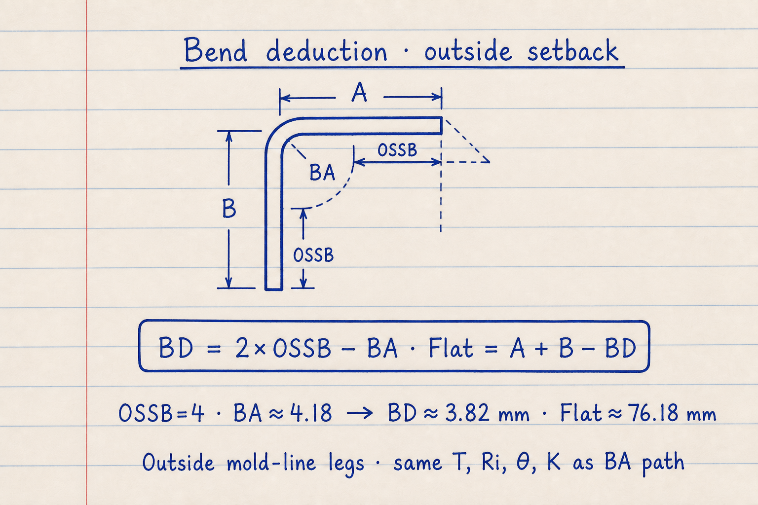
Dashed construction lines meet at the outside mold-line apex. Legs A and B run to that apex; each OSSB is the setback from the apex to the bend tangent.
BD = 2×OSSB − BA · Flat = A + B − BD. Same defaults: OSSB=4, BA≈4.18 → BD≈3.82 mm · Flat≈76.18 mm in Outside mold lines mode.
What bend angle θ means here
Enter the formed bend angle: how many degrees the sheet turns through the bend. A right-angle bracket uses θ = 90°. An acute formed bend of 60° uses θ = 60° in the BA and OSSB formulas.
Do not enter the open included angle of a channel if that angle is the complement of the bend. If your drawing labels the inside corner as 120° open, the formed bend is 60°. Wrong θ scales BA and BD in proportion and will not match a brake table.
Common formed-angle checks:
| Finished corner | Enter θ | Notes |
|---|---|---|
| Right-angle L-bracket | 90° | Default on this pad |
| 60° formed bend | 60° | Acute formed angle |
| 120° open inside corner | 60° | Formed bend = 180° − open angle |
| 45° hem prep (formed) | 45° | Same BA formula; check min flange separately |
Material presets are starting points only
The Material preset menu fills a typical handbook-style K so you can screen a blank quickly. It is not a substitute for a supplier bend chart or your own coupon test on that thickness, punch radius, and V-die.
When you type a custom K, the preset drops back to Custom K-factor. Keep units consistent: Metric keeps all lengths in mm, Imperial in inches. Switching tabs converts the length fields so mm and inch values do not mix quietly.
Preset K values on this pad:
| Preset | Starting K | Use when |
|---|---|---|
| Custom K-factor | You type it (default 0.33) | Shop table or test coupon |
| Mild steel (typical) | 0.42 | First-pass CRS / mild screen |
| Aluminum (typical) | 0.35 | Soft aluminum air bend screen |
| Stainless steel (typical) | 0.45 | Austenitic stainless screen |
| Copper (typical) | 0.35 | Soft copper screen |
| Brass (typical) | 0.38 | Common brass screen |
Worked example
Metric defaults: Bend-line flanges, T = 2 mm, θ = 90°, Rᵢ = 2 mm, K = 0.33, Leg A = Leg B = 40 mm.
- Leave Metric and Bend-line flanges selected. Confirm Custom K-factor = 0.33 and both legs 40 mm.
- Rₙ = 2 + 0.33 × 2 = 2.66 mm. BA = (π/180) × 90 × 2.66 ≈ 4.18 mm.
- OSSB = tan(45°) × (2 + 2) = 4.00 mm. BD = 2 × 4.00 − 4.18 ≈ 3.82 mm.
- Click CALCULATE. Flat pattern = 40 + 40 + 4.18 = 84.18 mm. Neutral radius 2.66 mm, outside radius 4.00 mm.
- Optional check: switch to Outside mold lines with the same 40 mm legs and CALCULATE again. Flat becomes 40 + 40 − 3.82 = 76.18 mm.
Result: Bend-line mode: BA 4.18 mm, BD 3.82 mm, OSSB 4.00 mm, flat 84.18 mm. Outside mold-line mode with the same numbers: flat 76.18 mm.
When to use
- Developing a single-bend flat blank before laser, punch, or shear
- Converting a print that dimensions to bend lines vs outside mold lines
- Screening BA and BD when you only have thickness, Ri, angle, and a starting K
- Cross-checking a CAD unfold or brake table entry for one bend
Limitations
- Single bend only. Multi-bend parts need one run per bend (or a full unfold in CAD).
- Air-bend K-factor model. No springback compensation in the flat length.
- Material presets are typical starting K values, not certified shop bend tables.
- Does not check minimum flange length, die width, or cracking (use min bend radius separately).
- Bend angle must be the formed bend (1° to 179°). θ = 180° is blocked because outside setback uses tan(θ/2).
- 3D sketch is teaching geometry only. It is not a toolpath or springback simulation.
FAQ
- Why does Flat change when I switch Bend-line vs Outside mold lines?
- BA and BD stay the same. Bend-line mode adds BA to flanges measured to the bend tangents. Outside mold-line mode subtracts BD from flanges measured to the outside apex. Same 40 mm legs give 84.18 mm vs 76.18 mm on the Metric defaults because those 40 mm lengths mean different things in each mode.
- What K-factor should I enter?
- Use your shop bend table or a measured coupon when you have one. If you only need a first pass, pick a material preset or start near 0.33 to 0.45. This pad accepts K from 0.20 to 0.50.
- Is bend angle the inside corner on my drawing?
- Enter the formed bend angle θ used in BA = (π/180) × θ × (Ri + K × T). A right-angle part uses 90°. If the drawing shows a 120° open inside corner, the formed bend is usually 60°. This pad accepts 1° to 179°.
- Why is 180° not allowed?
- Outside setback and bend deduction use tan(θ/2). At 180°, θ/2 is 90° and that tangent is undefined, so OSSB and BD are not usable. Use a formed angle at or below 179°, or handle a full hem with a dedicated hem process.
- How do I get flat length from bend deduction only?
- When both legs are outside mold-line dimensions, Flat = Leg A + Leg B − BD. That is what Outside mold lines mode does. If your legs are already to the bend lines, use Bend-line flanges and Flat = A + B + BA instead.
- Does Imperial use the same formulas?
- Yes. Keep every length in inches under the Imperial tab. The angles and K-factor are unchanged. RESET loads the inch equivalents of the 2 mm / 40 mm Metric defaults.
- Can I unfold a U-channel with two bends?
- Not in one click. Run each bend (or each unique bend setup) separately, then combine the straight segments and BA or BD values. For production multi-bend parts, confirm the full flat in your CAD sheet-metal environment.
- Why is outside setback useful if I already have BA?
- OSSB ties the outside mold-line apex to the bend tangents. You need it to form BD = 2 × OSSB − BA, and to convert between outside dimensions and bend-line flange lengths (bend-line leg ≈ outside leg − OSSB for a symmetric 90° case).
Minimum Bend Radius Calculator
Sheet metal minimum inside bend radius from material, temper, method, grain, and thickness. Optional desired-radius check. Metric or Imperial.
Open calculatorPunch and Die Design Calculator
Die clearance, cutting force, stripper, tonnage, and punch or die size for blanking, piercing, notching, cutoff, lancing, trimming, shaving, and perforating.
Open calculator