MMC / LMC clearance · live
- Fit type
- Clearance
- Min clearance
- 0.020 mm
- Max clearance
- 0.054 mm
- Mean clearance
- 0.037 mm
- Hole MMC / LMC
- 25.000 / 25.021 mm
- Shaft MMC / LMC
- 24.980 / 24.967 mm
Hole MMC − shaft MMC (tightest)
Hole LMC − shaft LMC (loosest)
Smallest / largest hole
Largest / smallest shaft
Preview updates as you type. Press CALCULATE to lock Results for this set of inputs.
A shaft must go through a hole — and you need the worst-case gap or interference from drawing deviations. This pad turns hole and shaft nominals plus upper/lower deviations into MMC and LMC sizes, min/max clearance, and a clearance / transition / interference label. Switch on Size + geometric to add virtual-condition go-gauge envelopes and optional MMC bonus from actual sizes.
Defaults open on Metric · Size only: 25 mm hole 0/+0.021, shaft −0.033/−0.020 (H7/h6 style). CALCULATE returns hole MMC 25.000 / LMC 25.021, shaft MMC 24.980 / LMC 24.967, min clearance 0.020 mm, max 0.054 mm — Clearance. Add geometric diameter 0.05 on both features for the VC path. Math stays in your browser.
It sits under GD&T & Metrology Calculators next to the GD&T true position calculator and ISO 286 tolerance calculator. This pad is a shaft-hole MMC/LMC fit check — not a full ISO fit-class picker or CMM position report.
Formula
- Hole MMC = smallest hole (most material). Hole LMC = largest hole.
- Shaft MMC = largest shaft (most material). Shaft LMC = smallest shaft.
- Min clearance = hole MMC − shaft MMC (tightest assembly).
- Max clearance = hole LMC − shaft LMC (loosest assembly).
- Clearance if min ≥ 0 · Interference if max ≤ 0 · else Transition.
- VC_hole = MMC_hole − geometric tol · VC_shaft = MMC_shaft + geometric tol (go-gauge).
- Hole bonus = max(0, actual − MMC) · Shaft bonus = max(0, MMC − actual).
Reproduce the default Metric size-only path on CALCULATE:
| Quantity | Value |
|---|---|
| Inputs | Hole 25 0/+0.021 · Shaft 25 −0.033/−0.020 |
| Hole MMC / LMC | 25.000 / 25.021 mm |
| Shaft MMC / LMC | 24.980 / 24.967 mm |
| Min / max clearance | 0.020 / 0.054 mm → Clearance |
| VC example | Geo 0.05 both → hole VC 24.950 · shaft VC 25.030 · VC gap −0.080 |
How it works
MMC is most material (smallest hole, largest shaft) — the tightest assembly condition. LMC is the opposite. Min clearance = hole MMC − shaft MMC. Optional geometric tolerances build virtual condition go-gauge envelopes; actual sizes unlock MMC bonus.
Pick Metric or Imperial (tab switch resets defaults). Choose Size only or Size + geometric. Enter hole and shaft nominals with upper/lower deviations (as on the print). Geometric mode unlocks geo. tol. diameter and optional actual sizes for bonus. CALCULATE locks Results and the live MMC/LMC cross-section sketch (Play/Pause; gaps exaggerated for teaching). Editing clears Results. RESET restores the active tab's size-only defaults.
MMC vs LMC — most material, not “biggest number”
Maximum Material Condition defines MMC as the state with the most material inside the size tolerance: for a pin that is the largest diameter; for a hole it is the smallest diameter. Both extremes make assembly hardest.
LMC is the opposite: smallest shaft, largest hole. Default GD&T (no Ⓜ or Ⓛ) is RFS — geometric control holds regardless of size and there is no bonus. This pad’s size-only mode is the MMC/LMC limit stack used for fit; geometric mode adds the virtual-condition envelope.
Material condition quick map:
| Feature | MMC | LMC | Fit effect |
|---|---|---|---|
| Shaft / pin | Largest Ø | Smallest Ø | MMC = tightest |
| Hole / bore | Smallest Ø | Largest Ø | MMC = tightest |
| Assembly | Hardest to assemble | Loosest / easiest | Use for worst-case stack |
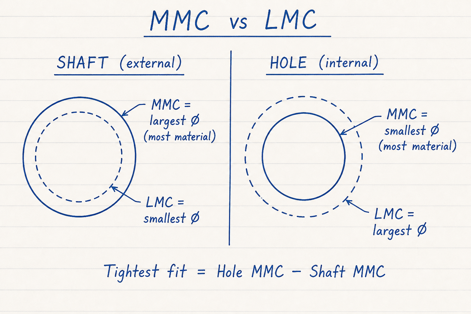
Shaft MMC = largest pin; hole MMC = smallest bore — both leave the most material.
Tightest size fit = hole MMC − shaft MMC.
Min and max clearance — classifying the fit
MMC creates the tightest allowable fit — not automatically an interference fit. Whether you get clearance, transition, or interference depends on the tolerance stack between hole and shaft.
Min clearance uses the small hole with the large shaft. Max clearance uses the large hole with the small shaft. Min ≥ 0 → clearance (includes line-to-line). Max ≤ 0 → interference. A sign change across the range is a transition fit.
Default 25 mm H7/h6-style example:
| Limit | Value (mm) | Role |
|---|---|---|
| Hole MMC | 25.000 | Smallest hole |
| Shaft MMC | 24.980 | Largest shaft |
| Min clearance | 0.020 | Tightest gap |
| Max clearance | 0.054 | Loosest gap |
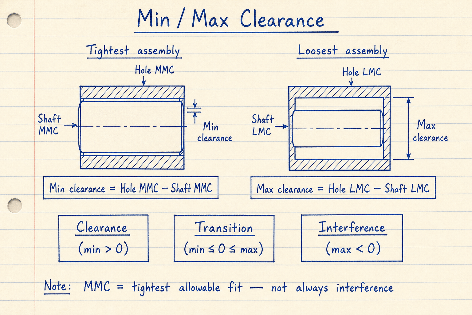
Default CALCULATE path: 0.020 to 0.054 mm → Clearance.
MMC is worst-case for assembly; LMC is worst-case for loose alignment or wall material.
Virtual condition and go-gauges
When size and a geometric tolerance (position, perpendicularity, …) are specified at MMC, they form a fixed functional boundary — the virtual condition. A hole is gauged with a pin of size MMC − geometric tol, and a pin with a ring of size MMC + geometric tol. A worked Ø20 ±0.1 shaft with 0.05 position at MMC gives VC = 20.1 + 0.05 = 20.15 mm — a fixed go-ring that checks size and orientation together.
As the feature departs from MMC toward LMC, bonus tolerance grows by the same amount and the virtual condition stays constant — that is why MMC callouts cut scrap on assembly-critical parts. Use LMC when minimum wall or material around a hole matters; use RFS when alignment must hold at every size (for example a bearing bore).
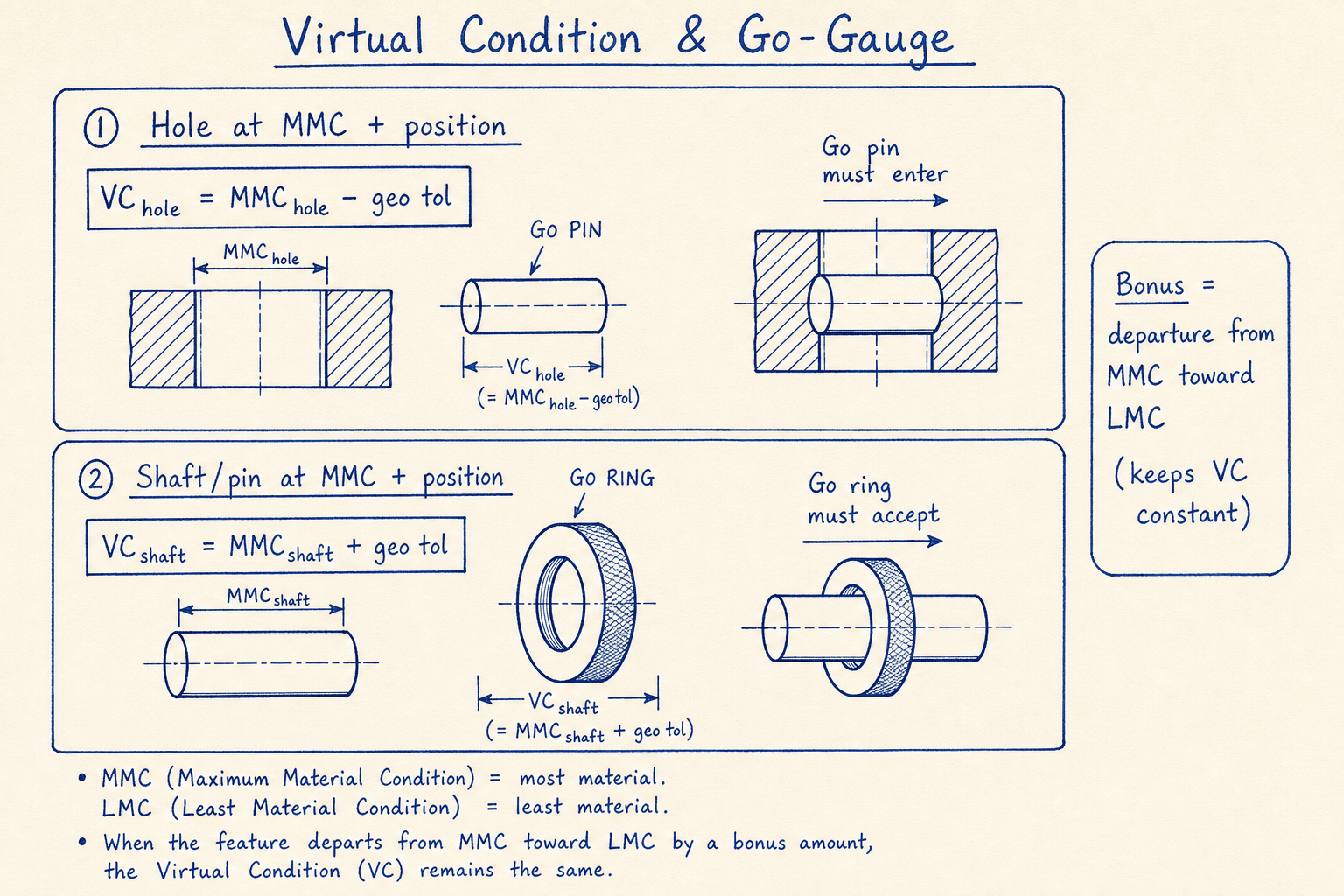
Hole VC = MMC − geo tol (go pin). Shaft VC = MMC + geo tol (go ring).
Optional actual sizes on this pad report MMC bonus = departure toward LMC.
Worked example
Default Metric · Size only: 25 mm hole 0/+0.021, shaft −0.033/−0.020. Reproduce on CALCULATE.
- Leave Metric and Size only. CALCULATE → hole MMC 25.000 / LMC 25.021 · shaft MMC 24.980 / LMC 24.967.
- Min clearance = 25.000 − 24.980 = 0.020 mm · max = 25.021 − 24.967 = 0.054 mm → Clearance.
- VC example: Size + geometric, geo ∅ 0.05 on both → hole VC 24.950 · shaft VC 25.030 · VC clearance −0.080 mm.
- Shaft-style example: 20 ±0.1 with geo 0.05 → shaft MMC 20.1 · shaft VC 20.15 mm.
Result: Default: Clearance fit 20–54 µm. Geometric mode shows the go-gauge envelope when form is called at MMC.
When to use
- Checking shaft-hole fit from drawing size deviations
- Finding min/max assembly clearance at MMC and LMC
- Classifying clearance, transition, or interference
- Building virtual-condition go-gauge sizes from geometric tol at MMC
- Estimating MMC bonus from measured actual sizes
Limitations
- Manual deviation entry — not a full ISO 286 fit-class lookup (use the ISO 286 calculator for H7/g6 tables).
- Geometric mode models a single diametral geo tol per feature; not full FCF datum frames.
- Does not compute true position from X/Y CMM data (use the true position calculator).
- Bonus is reported from optional actual sizes; it does not alter the size clearance stack.
- Assumes cylindrical features; no taper, thread, or projected-zone modeling.
FAQ
- What is MMC for a hole?
- Maximum Material Condition for a hole is its smallest allowable diameter — the condition with the most material remaining around the hole. For a shaft, MMC is the largest diameter.
- Does MMC always mean interference?
- No. MMC is the tightest allowable fit (hardest to assemble). Whether that stack is clearance, transition, or interference depends on the hole and shaft limits.
- Min clearance vs max clearance?
- Min clearance uses the tightest assembly (small hole, large shaft). Max clearance uses the loosest (large hole, small shaft). Negative clearance is interference.
- What is virtual condition?
- The fixed functional envelope when size MMC and a geometric tolerance are combined: hole VC = MMC − geo tol; shaft VC = MMC + geo tol. A go-gauge at that size checks size and form together.
- When should I use LMC or RFS instead of MMC?
- Use LMC when minimum wall thickness or material around a feature matters. Use RFS when geometric control must hold at every size (for example bearing bores). Prefer MMC for assembly/fit and functional gauging.
GD&T True Position Calculator
Diametral true position from X/Y deviations with RFS, MMC, or LMC bonus — Metric or Imperial, 2D or 3D.
Open calculatorISO 286 Tolerance Calculator
ISO 286 hole/shaft limits, deviations, and clearance / transition / interference fit type.
Open calculatorLocating Pin Fit Calculator
Pin–hole clearance, transition, or interference from ISO-style deviations, plus Lamé press-force screening.
Open calculator