Blanking
Die controls blank size
- Punch
- — mm
- Die
- — mm
- Clearance
- — / — mm
- Tonnage
- — T
- Clearance per side
- n/amm
- Total clearance
- n/amm
- Shear strength τ
- n/aMPa
- Perimeter used
- n/amm
- Cutting force
- n/akN
- Stripper force
- n/akN
- Total design force
- n/akN
- Press tonnage
- n/aT
- Punch size
- n/amm
- Die size
- n/amm
You need punch and die sizes with a workable clearance, plus a first-pass press tonnage before you pull a tooling quote. This pad covers eight shear operations — blanking, piercing, notching, cutoff/parting, lancing, trimming, shaving, and perforating — for circular, rectangular, square, or custom-perimeter cuts.
Defaults open on blanking a 25 mm round in 2 mm mild steel at 5% clearance per side and UTS 420 MPa. CALCULATE returns c = 0.1 mm, F_cut ≈ 52.78 kN, design tonnage ≈ 6.73 T, punch 24.8 mm, and die 25.0 mm. Each operation draws a distinct Results sketch. Material chips set aluminum, mild steel, or stainless UTS with typical unitized-punching clearance suggestions. Math stays in your browser.
It lives under Manufacturing Calculators. After the blank looks right, unfold flanges on the sheet metal bend calculator or check air-bend limits on the minimum bend radius calculator.
Formula
- Clearance per side c = (% / 100) × thickness. Total clearance = 2c.
- Shear strength τ = 0.8 × UTS (MPa).
- Cutting force F_cut (kN) = τ × t × perimeter / 1000.
- Stripper force = 0.15 × F_cut. Total design force = F_cut × 1.25 × strokes.
- Press tonnage (metric T) = total design force / 9.81.
- Blanking: punch = size − 2c, die = size. All other ops on this pad: punch = size, die = size + 2c.
Default blanking path (Ø25 mm, t = 2 mm, UTS 420 MPa, 5% per side, 1 stroke):
| Quantity | Value on this pad |
|---|---|
| Perimeter L | π × 25 ≈ 78.54 mm |
| τ = 0.8 × UTS | 336 MPa |
| Clearance c / total | 0.100 mm / 0.200 mm |
| Cutting force F_cut | 52.78 kN |
| Total design force | 65.97 kN |
| Press tonnage | 6.73 T |
| Punch / die | 24.800 mm / 25.000 mm |
How it works
Cutting force uses shear strength approximated as 0.8 times UTS times shear perimeter times thickness. Clearance per side is a percentage of sheet thickness. Blanking sizes the die to the blank; piercing, notching, cutoff, lancing, trimming, shaving, and perforating size the punch to the feature. Press tonnage converts total design force to metric tons.
Choose the shear operation (Blanking through Perforating), then the cut shape. Enter size (diameter, rectangle, square side, or custom perimeter), thickness, UTS, and clearance % per side. Material chips fill UTS and a suggested clearance (aluminum 7.5%, mild steel 10%, stainless 12.5% per side). CALCULATE fills Results and updates the operation-specific punch/die sketch. Editing a field clears Results. RESET restores the Ø25 blanking defaults at 5% clearance.
Blanking puts size on the die; other ops put size on the punch
In blanking the slug is the part. The die opening sets the blank outline, so die = size and the punch is smaller by total clearance (2c). In piercing the hole is the feature. The punch sets the hole, so punch = size and the die is larger by 2c. Notching, cutoff/parting, lancing, trimming, shaving, and perforating on this pad follow that same punch-controls-size rule.
Reproduce the defaults on CALCULATE for blanking Ø25: punch 24.8 mm, die 25.0 mm. Switch Operation to Piercing with diameter 20 mm and the same 5% clearance: punch 20.0 mm, die 20.2 mm. Results redraws a distinct sketch for each operation.
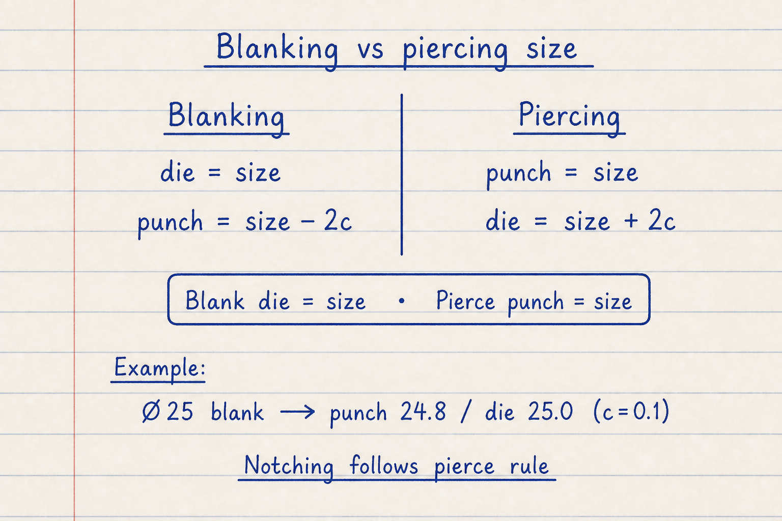
Blanking: die = size, punch = size − 2c. Other ops: punch = size, die = size + 2c.
Default blanking Ø25 at c = 0.1 mm → punch 24.8 mm / die 25.0 mm after CALCULATE.
Eight shear operations on this pad
Blanking drops the slug as the part. Piercing leaves a hole and drops scrap. Notching takes an open cut from a strip edge. Cutoff/parting shears across the strip to separate a length. Lancing cuts and forms a tab that stays attached. Trimming shears outer scrap from a formed blank. Shaving is a thin secondary cut for edge finish (shops often use tighter clearance — override %). Perforating is multi-hole punching; set Punches / strokes to the holes that fire together.
Force still uses F = τ·t·L for the shear perimeter you enter. The operation choice mainly picks the punch/die sizing rule and the Results diagram. It is not a progressive-die station stack.
Clearance percent: shop totals versus per-side on this pad
Many unitized punching charts publish blanking and piercing clearance as a fraction of thickness for the full die opening (total diametral gap). Common unitized-punching charts use about 15% of t for aluminum, 20% for mild steel, and 25% for stainless as that total. This pad stores clearance per side, so those totals become 7.5%, 10%, and 12.5%.
Defaults stay at 5% per side so the worked example matches the verify path. Tap Mild steel, Aluminum, or Stainless to load the suggested % and a typical UTS. Override either field when your grade or edge-quality target differs. Too little clearance raises force and wear; too much grows burr and fracture zone.
Material chip suggestions on this pad:
| Material | UTS filled | % per side | Implied total |
|---|---|---|---|
| Aluminum | 200 MPa | 7.5% | 15% |
| Mild steel | 420 MPa | 10% | 20% |
| Stainless | 520 MPa | 12.5% | 25% |
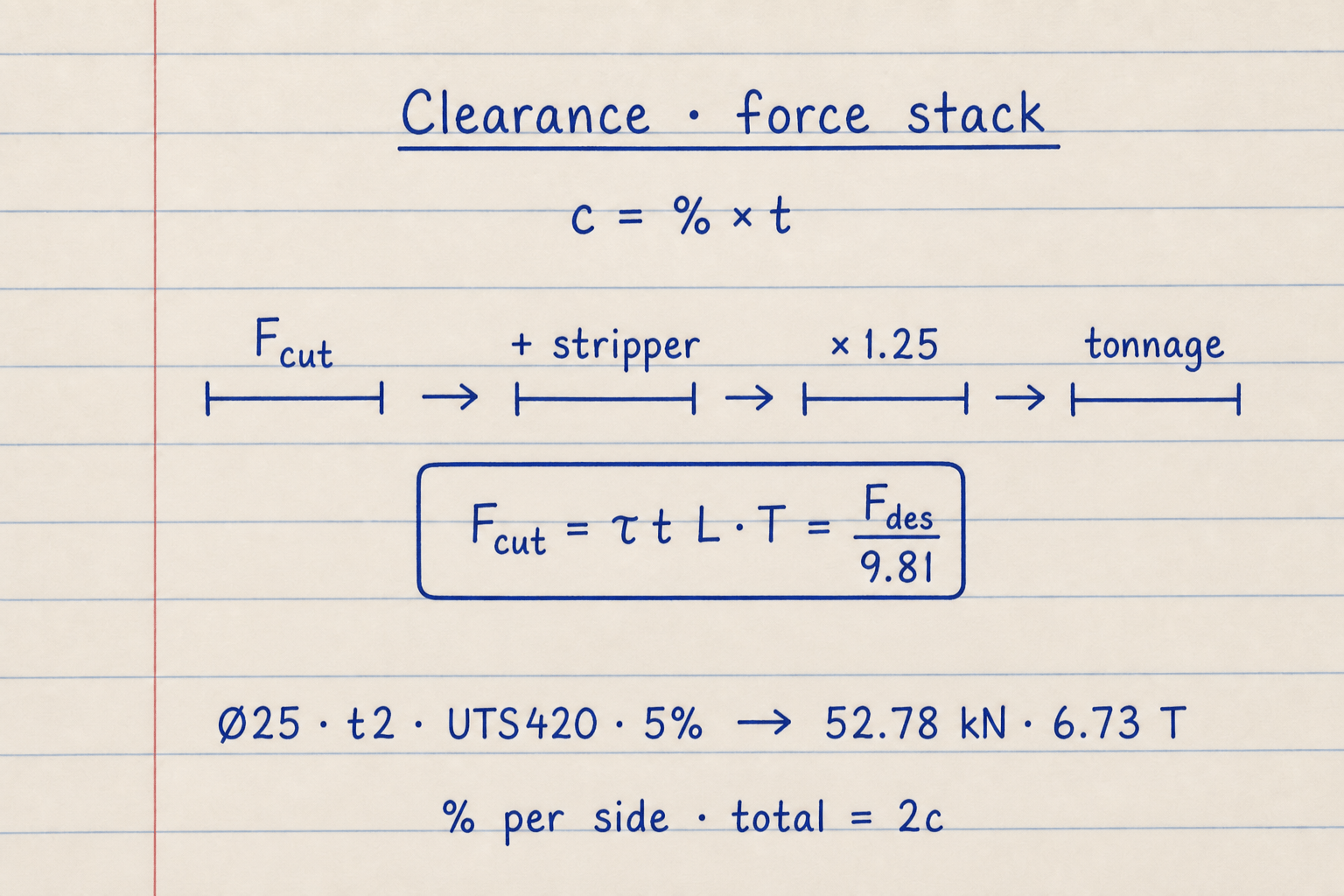
c = % × t (per side). F_cut = τ × t × L, then stripper and ×1.25 design factor to tonnage.
Default path: Ø25 · t2 · UTS 420 · 5% → 52.78 kN · 6.73 T. Total clearance = 2c.
Cutting force uses perimeter, thickness, and shear strength
F_cut = τ × t × L, with L from the shape (πD for a round). Shear strength is taken as 0.8 × UTS here. Some teaching tools use about 0.7 × tensile strength. The higher factor is intentional for a conservative first press pick.
On the defaults, τ = 336 MPa, L ≈ 78.54 mm, t = 2 mm → F_cut ≈ 52.78 kN. Stripper is shown as 15% of F_cut for planning the stripper springs. Total design force multiplies F_cut by 1.25 and by the number of simultaneous punches, then divides by 9.81 for metric tons.
What this calculator is not
It is not a progressive-die station stack, not a punch-face shear-angle force reducer, and not a fine-blanking model with near-zero clearance. Deep shear mechanics notes live on shearing (manufacturing). Production tools still need supplier charts, tryout, and press capacity with your plant safety factor.
Metric units only on this pad (mm, MPa, kN, metric tons). Confirm nameplate tonnage units before you size a press.
Worked example
Blanking · Circular defaults: Ø25 mm, t = 2 mm, UTS 420 MPa, 5% clearance per side, 1 stroke. Reproduce on CALCULATE.
- Leave Operation on Blanking and Cut shape on Circular. Confirm diameter 25, thickness 2, UTS 420, clearance 5, strokes 1.
- CALCULATE. Perimeter = π × 25 ≈ 78.54 mm. τ = 0.8 × 420 = 336 MPa.
- c = 0.05 × 2 = 0.1 mm. Punch = 25 − 0.2 = 24.8 mm. Die = 25 mm.
- F_cut = 336 × 2 × 78.54 / 1000 ≈ 52.78 kN. Total design force ≈ 65.97 kN. Tonnage ≈ 6.73 T.
- Optional: switch to Piercing, set diameter 20, CALCULATE. Punch 20.0 mm, die 20.2 mm. Try Cutoff, Lancing, Trimming, Shaving, or Perforating to see each Results sketch (same punch-size rule as piercing).
Result: Default blanking: punch 24.8 mm, die 25.0 mm, F_cut 52.78 kN, tonnage 6.73 T. Piercing Ø20 at 5%: punch 20.0 mm, die 20.2 mm. Other ops (3–7) use the same punch-size rule.
When to use
- First-pass press tonnage for blanking, piercing, or related shear ops
- Punch and die sizes with a stated clearance percent
- Comparing mild steel vs stainless clearance suggestions before tryout
- Estimating stripper load and multi-punch stroke count (perforating)
- Homework checks of F = τ·t·L with round or rectangular perimeters
Limitations
- Shear strength fixed at 0.8 × UTS. Real grades vary; override UTS or treat τ as approximate.
- No progressive-die station stacking, compound tools, or punch-face shear angle.
- Not fine blanking or near-zero clearance (shaving often wants tighter c — override %).
- Clearance chips are teaching estimates, not a supplier AHSS chart.
- Operation mode selects sizing rule and sketch only; force always uses the entered perimeter.
- Rectangular punch/die size uses the larger side only (force still uses the full 2(L+W) perimeter). Square and round apply clearance on that one dimension.
- Custom-perimeter punch/die size uses an equivalent diameter = perimeter / π for the clearance offset only.
- Stripper force is shown separately; total design force is F_cut × 1.25 × strokes (stripper not added again).
- Metric only (mm, MPa, kN, metric tons).
- Not a substitute for tooling supplier data or stamped press capacity checks.
FAQ
- Blanking vs piercing: which size goes on the punch?
- Blanking: die equals the blank size and punch is smaller by total clearance. Piercing, notching, cutoff, lancing, trimming, shaving, and perforating: punch equals the feature size and die is larger by total clearance.
- What do cutoff, lancing, trimming, shaving, and perforating change?
- They use the same punch = size, die = size + 2c rule as piercing, and each draws a different Results sketch. Force still comes from perimeter × thickness × shear strength. For perforating, set Punches / strokes to how many holes fire on one press stroke.
- Is clearance percent per side or total?
- This pad uses percent of thickness per side. Total (diametral) clearance is 2 × per side and appears on the Results card. Material chips convert common total charts (15/20/25%) into 7.5/10/12.5% per side.
- Why 0.8 × UTS for shear strength?
- Punching shear strength is often about 60–80% of tensile strength. This tool uses 80% so the first tonnage pick is on the conservative side of that band.
- What does the 1.25 factor mean?
- Total design force multiplies cutting force by 1.25 as a simple design allowance, then by the number of simultaneous punches. It is not a plant-specific safety factor.
- Why is stripper force shown separately?
- After the cut, the sheet can grip the punch. Stripper force is estimated as 15% of cutting force for spring or stripper-plate planning. Peak press demand still follows the total design force card.
- Can I model progressive dies?
- No. Enter strokes only for punches that fire on the same press stroke. Multi-station progressive force stacking needs a dedicated process sheet.
- What shape should I pick for an odd outline?
- Use Custom perimeter and enter the full shear length in millimetres. Punch/die size for custom shapes uses an equivalent diameter from perimeter / π for the clearance offset only.
Sheet Metal Bend Allowance Calculator
Bend allowance, bend deduction, outside setback, and flat blank from thickness, inside radius, K-factor, and flange measure mode. Metric or Imperial.
Open calculatorMinimum Bend Radius Calculator
Sheet metal minimum inside bend radius from material, temper, method, grain, and thickness. Optional desired-radius check. Metric or Imperial.
Open calculatorWeld Joint Strength Calculator
Fillet and groove weld capacity for tee, lap, corner, edge, and butt joints — throat, stress, and factor of safety.
Open calculator