A drawing calls out Ra 1.6 µm. The gauge report is in µin. A supplier quotes N7. Another print shows Rz. This pad converts between Ra, Rz, Rq/RMS, Rt, CLA, and ISO N-grades with a process-based Rz/Ra screening factor — then shows a statistical Rz band so you see how wide the estimate really is.
Defaults open on Ra 1.6 µm · Typical screening (×6). CALCULATE returns Rz 9.6 µm, Rq ≈ 1.78 µm, Rt 12 µm, Ra ≈ 63 µin, closest N7, and a Rz band of about 6.4–12.8 µm. Switch ×5 or ×7 chips when that matches your shop chart. Math stays in your browser.
It sits under GD&T & Metrology Calculators next to the ISO 286 tolerance calculator and GD&T fit calculator. This pad is a unit / grade converter — not a turning feed-from-Ra tool.
Formula
- Ra (µin) = Ra (µm) × 39.3701. CLA = Ra in µin.
- Rq ≈ RMS ≈ 1.11 × Ra (Gaussian surface screening).
- Rz ≈ k × Ra where k is the process factor (Typical ×6, chart ×5, CNC turning ×7, …).
- Statistical Rz band used here: about 4×Ra to 8×Ra.
- Rt ≥ Rz; this pad uses Rt ≈ max(7.5, 1.25×k) × Ra as a screening estimate.
- ISO 1302 N1–N12 map to fixed Ra maxima (N6 = 0.8 µm, N7 = 1.6 µm, N8 = 3.2 µm).
Reproduce the default Ra 1.6 µm · Typical ×6 path on CALCULATE:
| Quantity | Value |
|---|---|
| Inputs | Ra 1.6 µm · Typical screening (×6) |
| Rz (mean) | 9.6 µm |
| Rz band | ≈ 6.4–12.8 µm |
| Rq / RMS | ≈ 1.78 µm · ≈ 70 µin |
| ISO grade | N7 · Ra ≈ 63 µin (CLA) |
How it works
Enter Ra, Rz, Rq, Rt, µin, RMS, or an ISO N-grade. Process chips set the Rz/Ra screening factor. Results show metric and imperial equivalents, a statistical Rz band, and the closest N-grade. Ra↔Rz is approximate — measure the drawing parameter for critical work.
Choose Input parameter (Ra / Rz / Rq / Rt / µin / RMS / N-grade). Pick a Process Rz/Ra factor or tap a chip (Typical ×6, chart ×5, CNC ×7, Grind, Lap) — the live profile updates the mean Rz estimate with the factor even before CALCULATE. Enter the value (or whole-number N-grade). CALCULATE fills all equivalents, the Rz band, and dual µm/µin. Editing clears Results. RESET restores Ra 1.6 µm · Typical ×6.
Ra, Rz, RMS — what converts cleanly
Surface finish converters agree on the easy links: CLA equals Ra in microinches, RMS ≈ 1.11 × Ra, and N-grades are fixed Ra maxima under ISO 1302.
Ra↔Rz is the hard one. They measure different geometry. Only a statistical band is honest — not a single magic multiplier.
ISO 1302 N-grade → Ra (common machining range):
| N | Ra (µm) | Ra (µin) | Typical use |
|---|---|---|---|
| N5 | 0.4 | 16 | Fine ground |
| N6 | 0.8 | 32 | Fine turned / milled |
| N7 | 1.6 | 63 | As-machined CNC ★ |
| N8 | 3.2 | 125 | Rough machined |
| N9 | 6.3 | 250 | Very rough |
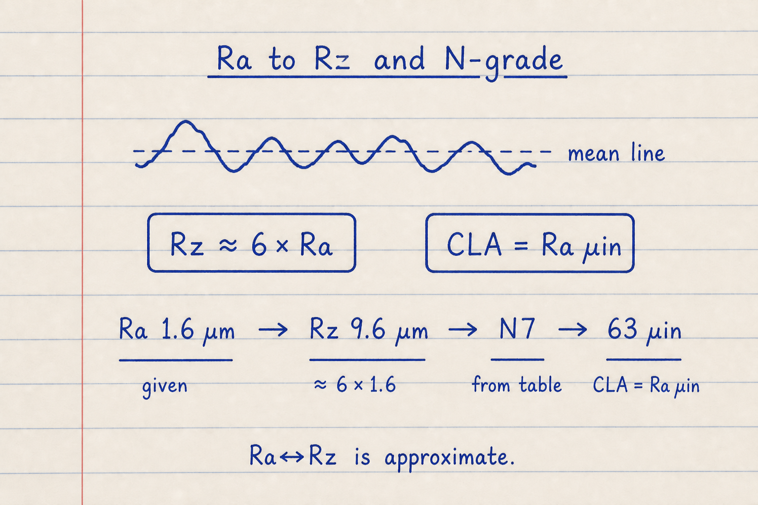
Default CALCULATE path: Ra 1.6 µm × 6 → Rz 9.6 µm; closest grade N7; CLA ≈ 63 µin.
Rq / RMS ≈ 1.11 × Ra for a Gaussian screening estimate.
Process Rz/Ra factors — shop chips
Process pickers let you choose a process so the Rz/Ra ratio changes — super-finishing near ×3.5, CNC turning near ×7, rough milling near ×8. Many public charts often use a flat ×5.
This pad ships both: a Typical ×6 default (keeps the historic screening path) plus ×5 and process chips. The mean Rz uses your factor; the Results card still shows a wider 4×–8× Ra band.
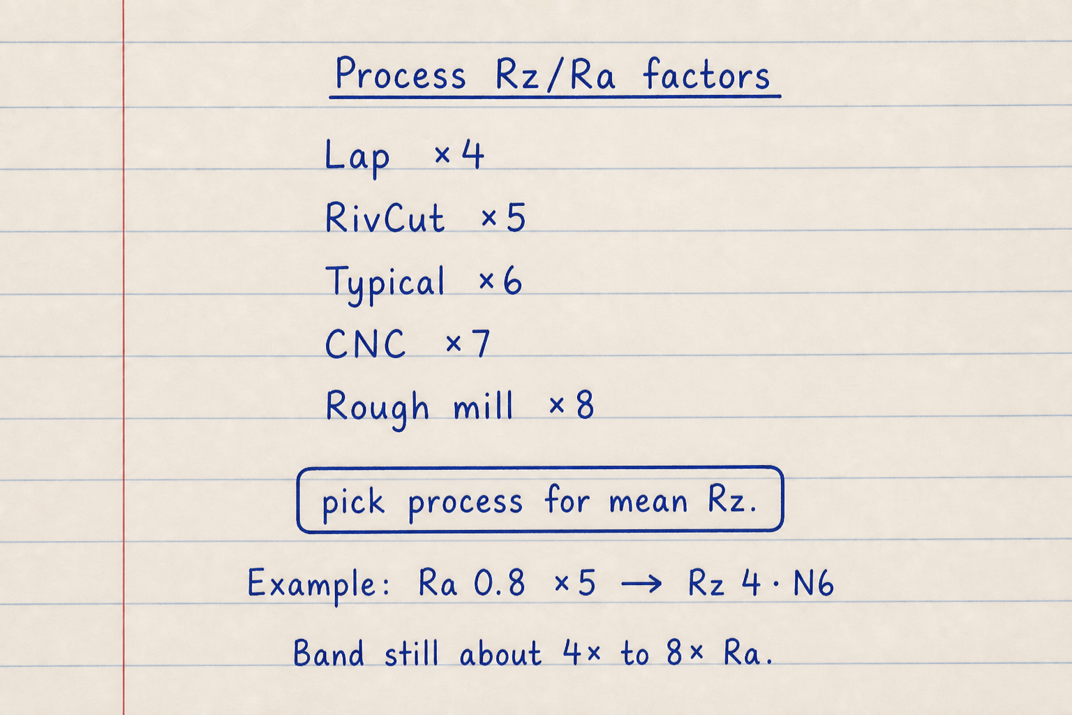
Chip examples: ×5 on Ra 0.8 µm → Rz 4 µm · N6; CNC ×7 on Ra 1.6 µm → Rz 11.2 µm.
Pick the process that matches how the surface was made when you only have Ra on the print.
What this pad does not do
Turning feed-and-radius finish predictors are a different job — out of scope here. Many Ra–Rz references quote a statistical band rather than one fixed multiplier; this pad shows a similar band on every CALCULATE.
Full ISO 1302 symbol builders, sampling-length λc pickers, and profile simulators stay on specialist tools. Use this hub for quick unit/grade screening before you measure the required parameter.
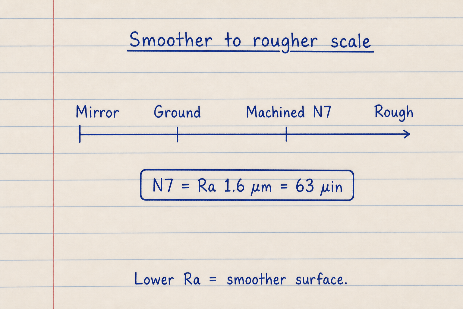
Visual scale idea: mirror / ground / machined / rough — lower Ra is smoother.
Standard CNC as-machined often lands near Ra 63 µin (N7).
Worked example
Default Ra 1.6 µm · Typical screening (×6). Reproduce on CALCULATE.
- Leave Input = Ra (µm), Process = Typical screening (×6), value 1.6.
- CALCULATE → Rz 9.6 µm · band ≈ 6.4–12.8 µm · Rq ≈ 1.78 µm · N7 · ≈ 63 µin.
- ×5 example: chip ×5, Ra 0.8 µm → Rz 4 µm · N6.
- CNC example: chip CNC ×7, Ra 1.6 µm → Rz 11.2 µm · still N7.
- µin example: Input Ra/CLA (µin) = 63 → Ra ≈ 1.60 µm · N7.
Result: Default: Ra 1.6 µm · Rz 9.6 µm · N7 · ≈ 63 µin CLA.
When to use
- Converting Ra ↔ µin / CLA / RMS for prints and CMM reports
- Estimating Rz from Ra with a process factor
- Mapping measured Ra to the closest ISO N-grade
- Seeing a statistical Rz band instead of a single false precision number
- Quick shop screening before quoting a finish
Limitations
- Ra↔Rz is approximate; process and material change the real ratio.
- Does not compute roughness from a raw profile trace.
- Does not predict Ra from turning feed and corner radius.
- N-grade uses closest log match to ISO 1302 Ra maxima.
- Not a full ISO 1302 drawing-symbol builder.
FAQ
- Ra vs Rz?
- Ra is the arithmetic average roughness. Rz averages peak-to-valley heights over sampling lengths and is more sensitive to outliers. Typical ratios run about 4–8× Ra; this pad’s process factor sets the mean estimate.
- Can I convert Ra to Rz exactly?
- No. Conversion references treat it as a statistical estimate. For critical specs, measure the parameter written on the drawing.
- What is N7?
- ISO 1302 N7 corresponds to a maximum Ra of 1.6 µm (about 63 µin) — a common as-machined CNC finish.
- What is CLA or RMS?
- CLA is the same as Ra in microinches. RMS (Rq) squares deviations before averaging and is about 1.11 × Ra for many surfaces.
- Why pick a process factor?
- Ground, lapped, and milled surfaces have different Rz/Ra ratios. Process factors (and flat ×5 charts) give a better mean than one fixed multiplier for every process.
ISO 286 Tolerance Calculator
ISO 286 hole/shaft limits, deviations, and clearance / transition / interference fit type.
Open calculatorGD&T Fit Calculator
Shaft-hole MMC/LMC clearance, fit type, and optional virtual-condition go-gauge envelopes.
Open calculatorMinimum Bend Radius Calculator
Sheet metal minimum inside bend radius from material, temper, method, grain, and thickness. Optional desired-radius check. Metric or Imperial.
Open calculator